Low-Loss LED Driver Improves a System's Green Footprint by Boosting Efficiency and Extending Battery Life
Abstract:?Providing power to drive high-brightness LEDs (HB LEDs) can be achieved by a number of different schemes. Because many systems are battery powered, energy efficiency is key to maximizing each battery charge and the system's operating time. By improving battery efficiency you also improve the system's "green" footprint. Over the life of the battery for the same number of charge cycles, longer times between charges translate into potentially hundreds of hours of additional use from the batteries. Thus fewer batteries may end up in landfills or hazardous waste-disposal sites.
The usual approach for low-power lighting is a simple linear regulator configured to operate in a constant-current mode (Figure 1a). This linear regulator offers the benefit of simple design. Its main disadvantage, however, is its high power loss, since the surplus headroom voltage is dissipated as heat in the current-measuring resistor and the regulator itself. This heat could also have a negative effect on the system's "green" footprint. More heat might require more cooling (a fan or large metal heatsink) which could consume still more energy, space, and weight while adding to materials cost and manufacturing time.
An alternative method employs a switch-mode-regulation scheme such as a buck or boost regulator (Figure 1b). These regulators often require a feedback voltage between 0.8V and 1.3V to regulate the current to the LED. The current-measurement scheme to set that voltage typically employs a low-value resistor in series with the LED. The voltage developed across this resistor provides the feedback voltage that maintains the constant-current power supply to the LED. The losses in the regulator can thus be reduced, but there are still losses in the system due to the power dissipated by the current-measuring resistor.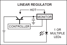
Figure 1a. A simple linear regulation scheme experiences power losses due to both the regulator and the current-setting resistor. The advantages of this circuit are its simplicity and the fact that it generates no EMI. The circuit can, however, only lower voltage and it does generate some heat.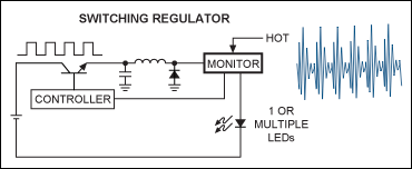
Figure 1b. In a basic switch-mode-regulation approach the main source of power loss comes from the energy dissipated by the current-sensing resistor. This design is highly efficient and can boost voltages. It is, however, a more complex circuit and can generate EMI.
To reduce the power loss due to the current in the resistor, a low-loss current-measuring scheme such as a resistor/amplifier combination can be incorporated to provide the required feedback voltage to the switching converter. One such approach employs a dedicated, precision current-sense amplifier such as the MAX9938H, which generates 100V/V sensed across the series current-measuring resistor. This approach reduces the losses in the feedback portion of the circuit to only a few milliwatts. The low-value sense resistor required can even be derived from a short length of copper trace on the board at zero cost, making this an attractive solution.
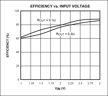
In the circuit shown in Figure 2, the boost converter configuration features the MAX9938H current-sense amplifier and uses a MAX8815A step-up converter to get its power from two NiMnH series-connected cells. The MAX8815A operates at switching frequencies up to 2MHz with efficiencies up to 97%. That high-switching frequency minimizes the size of external components; internal compensation further reduces the external component count for cost- and space-sensitive applications. The converter can generate any output voltage from 3.3V to 5V from a two-cell NiMH or NiCd source or a single-cell Li+/Li polymer battery. 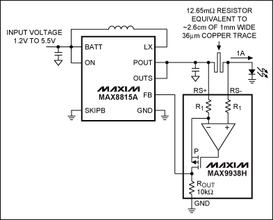
Figure 2. Working from Figure 1b, a current-sense amplifier such as the MAX9938H lowers the power losses in the current-sensing resistor to just a few milliwatts vs. hundreds of milliwatts, or more, for the previous schemes in Figure 1.
The MAX8815A has two operating modes: a low-power mode and a fixed-frequency, forced-PWM mode for heavy loads. Low-power mode consumes only 30μA of quiescent current and allows the converter to switch only when needed at no load and light loads. Low-power mode delivers the best efficiency for light loads and helps minimize wasted power and drain on the battery.
The second mode handles heavier loads (typically above 90mA) and uses a fixed-frequency forced-PWM scheme in which the converter switches at a fixed frequency irrespective of the load. This mode allows easy noise filtering and lower output ripple, but consumes more power.
For this application, the MAX8815A would be used in the higher power fixed-PWM mode and the shutdown pin would either enable or shut down the drive. In shutdown mode, the MAX8815A consumes only 100nA of current from the battery, thus prolonging the battery's operational life and the time required between recharges.
Along with the MAX8815A converter, the MAX9938H current-sense amplifier controls the current, thereby keeping a constant 1A flowing into the LED. This amplifier integrates the gain-setting resistors on its inputs for a gain of 100V/V. Additionally, it offers precision accuracy specifications with a VOS of less than 500μV (max) and a gain error of less than ±0.5% (max). The MAX9938H consumes just 1μA in its quiescent state. Other values of current can be achieved with a different value shunt resistor (possibly derived from a copper trace), perhaps modified or trimmed with a chip resistor in parallel.
This design approach presents a five-component solution and the battery's operational life is maximized since the power losses are minimized in both the regulator and the control loop. Samples and evaluation kits for the MAX8815A and MAX9938H are available now.
 電子發(fā)燒友App







評論