ICs Form Simple Thermometer-Style Voltage Indicator
Abstract:?This application note describes a circuit that produces a thermometer-style voltage indicator. The circuit illuminates a portion of 32 LEDs in continuous sequence starting from the bottom. The MAX4478 op amp is featured in the design.
This design idea appeared in the October 24, 2006 issue of EE Times magazine.
Unlike the analog D'Arsonval meter, a thermometer scale is an analog indicator with no moving parts. It is useful when you must acquire information quickly but do not need high accuracy. Typical applications for such a thermometer-style voltage indicator are control panels, vehicle dashboards, retrofits for pneumatic controls, and cosmetic indicators in entertainment equipment.
Oddly, a thermometer indicator takes an analog value, converts it to a digital number, and then displays that number in an analog format. The circuit in Figure 1 transforms its input voltage into time (a proportional pulse width). With 32 LEDs in a vertical column, it then displays an analog of the voltage by illuminating all the LEDs in sequence, from the lowest to the one that represents the input-voltage value.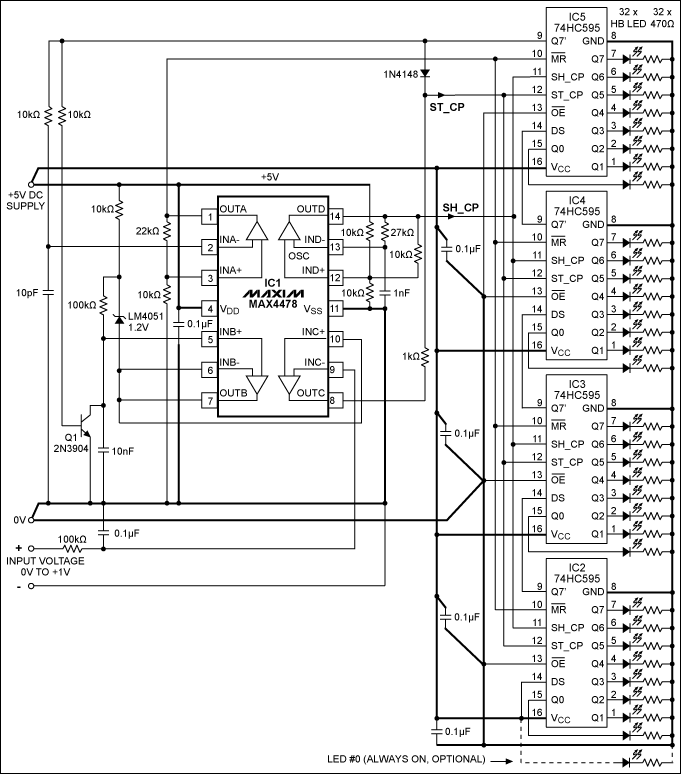
Figure 1. This circuit produces a "thermometer scale" by illuminating a portion of the 32 LEDs in continuous sequence from the bottom up.
At the beginning of each measurement cycle, a linear ramp generated by amplifier B in IC1 (the MAX4478 low-noise and low distortion op amp) is forced to zero by transistor Q1, and then restarted. All shift-register stages are set to digital zero as well. The MAX4478's amplifier C compares the ramp to the input voltage. When the input and ramp voltages are equal, the circuit generates a pulse.
The cascaded shift registers, IC2 to IC5, are also reset to zero at the start of a cycle. After that the shift function is driven by pulses from a clock oscillator (amplifier A on the MAX4478). The data input of the first shift register (IC2) is always connected to a high level (i.e., a logic "1"). When amplifier C on the MAX4478 detects that the input voltage and the ramp are equal, its low-to-high output edge feeds the ST_CP line. This, in turn, causes a transfer of data between the shift-register stages and their output registers.
All the shift-register stages, to which the digital "1" at the input of the shift-register chain has been already shifted, contain "1" as an output; all stages above that level contain "0." Upon transfer of data, the output registers copy the state of the shift-register stages. Each output register drives 1 LED in the column. The LEDs associated with digital "1s" are illuminated, thus producing a display similar to that of a thermometer.
After data from the shift register is transferred to the output registers, shifting of the input "1" continues through the shift-register chain until the first "1" reaches the top stage of the chain (IC5, Q7' output). This Q7' signal is applied to the base of Q1 and to the input of the MAX4478's amplifier A. Q1 resets the ramp. Amplifier A inverts and buffers the signal before feeding it to the shift registers' MR line, which zeroes all the shift-register stages (but not the output registers).
The comparator can never detect equality between ramp and input for overrange inputs. Therefore, the 1N4148 diode feeds the "1" from the top shift-register stage to the ST_CP line. It lights the entire column by causing a transfer of "1" to all the output registers. Linearity and stability are better than 1 LED step for the allowed range of input voltage (4.5V to 5.5V). You can add more steps (i.e., more LEDs) by adding extra shift-register ICs (each of which drives 8 LEDs), and by recalculating the ramp and clock periods. A timing diagram (Figure 2) gives the relative time relationships for the circuit's more important waveforms.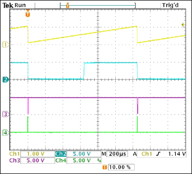
Figure 2. These waveforms illustrate the circuit operation in Figure 1. Trace 1: linear ramp generated by amplifier B of the MAX4478. Trace 2: output of amplifier C, which compares the ramp and input voltages. Trace 3: shift-register reset pulse generated by amplifier A. Trace 4: the last shift-register output.
 電子發(fā)燒友App




評(píng)論