Introduction
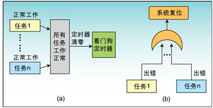
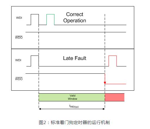
Today, microcontrollers are being used in harsh environments where electrical noise and electromagnetic interference (EMI) are abundant. In environments like this, it is beneficial if the system contains resources to help ensure proper operation. In many systems, a commonly used technique for verifying proper operation is the incorporation of a watchdog timer.A watchdog timer is fundamentally a time measuring device that is used in conjunction with, or as part of, a microprocessor and is capable of causing the microprocessor to be reset. In a properly designed system, the watchdog will cause a reset when the microprocessor is not operating correctly, thereby eliminating the faulty condition. In a typical application, the watchdog timer is configured to reset the processor after a predetermined time interval. If the processor is operating correctly, it will restart the watchdog before the end of the interval. After being restarted, the watchdog will begin timing another predetermined interval. If the watchdog is not restarted by the processor before the end of the interval, a watchdog timeout occurs. This results in the processor being reset. If the system software has been designed correctly, and there has been no hardware failure, the reset will cause the system to operate properly again. Of course, the reset condition must be a safe state. For instance, it would not be wise to have the reset state of a disk drive controller enabling the write head.
Many systems have been designed using an external watchdog timer. The need for this additional external component is eliminated, however, with the DS80C320. The DS80C320 contains its own, very capable internal watchdog timer. The features and the use of this watchdog timer are the subject of this application note.
General Use of a Watchdog Timer
The primary application of a watchdog timer is as a system monitor (as discussed in detail in the section below). With a watchdog timer, a system can be designed to be very good at detecting and correcting an out-of-control microprocessor. A system using a watchdog timer is particularly well suited to detecting bit errors. Momentary bit errors can be caused by such things as soft memory failures and electromagnetic discharges into memory devices and their interfaces. These can cause temporary bit polarity flipping of data into and out of the processor. When this occurs while fetching program information, the microprocessor will begin executing erroneous code. Potentially, the processor could begin executing operands instead of op-codes. When the processor begins executing this bad code, it will not properly execute the code that restarts the watchdog. After the timeout interval, the watchdog will cause a processor reset. In a properly designed system, the reset will correct the error.Regardless of how capable a watchdog timer might be, it cannot resolve all reliability issues. There are certain failures that cannot be corrected by a reset. For instance, a watchdog timer cannot prevent the corruption of data. In its basic form, the watchdog restart is dependent on proper program execution, and generally, does not depend on the values in data memory. Unless corruption of data affects program flow or some extra measures are taken, data corruption will not cause a watchdog timeout. Of course, self-diagnostic software can be written in such a way as to make restarting the watchdog contingent on verification of data memory. While this approach can be very effective and is quite common, it is beyond the scope of this document to discuss in detail.
Also note that a watchdog timer cannot detect a fault instantaneously. By definition, the watchdog timer must reach the end of a predetermined time interval before it resets the processor. This fact explains why a minimum possible timeout interval should be selected. In this way, a minimum amount of time expires before an out-of-control condition is corrected.
The Watchdog as a System Supervisor
The most common use of the High-Speed Micro's watchdog timer is as a system supervisor. While it can be used in a number of different ways, some of which will be discussed in this document, system supervisor is the most common application. In system supervisor mode, the timer is restarted periodically by the processor as described above. If the processor runs out of control, the watchdog will not be restarted; it will timeout, and subsequently will cause the processor to be reset.In the High-Speed Micro, the watchdog timer is driven by the main system clock that is supplied to a series of dividers. The divider output is selectable, and determines the interval between timeouts. When the timeout is reached, an interrupt flag will be set, and if enabled, a reset will occur 512 clocks later. The interrupt flag will cause an interrupt to occur if its individual enable bit is set and the global interrupt enable is set. The reset and interrupt are completely discrete functions that may be acknowledged or ignored, together or separately for various applications.
When using the watchdog timer as a system monitor, the watchdog's reset function should be used. If the interrupt function were used, the purpose of the watchdog would be defeated. To explain, assume the system is executing errant code prior to the watchdog interrupt. The interrupt would temporarily force the system back into control by vectoring the CPU to the interrupt service routine. Restarting the watchdog and exiting by an RETI or RET would return the processor to the lost position prior to the interrupt. By using the watchdog reset function, the processor is restarted from the beginning of the program, and thereby placed into a known state.
This is not to say that the DS80C320 watchdog's interrupt function is not useful for the system monitor application. Since the reset occurs 512 clocks after the interrupt, a short interrupt service routine can be used to store critical variables before the reset occurs. This may allow the system to return to proper operation in a state that more closely resembles the conditions before the failure. Of course, if the data is the source of the error, storing it without correction would be of no benefit. For any specific system, the approach taken is a function of the system and the level of reliability required.
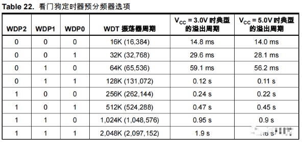
As mentioned above, the watchdog timer in the DS80C320 is driven by the main system clock that is passed through a series of dividers. The divider output may be selected by the user, allowing a timeout of 217, 220, 223, or 226 clocks. If enabled, a reset of the processor will occur 512 clocks later. Table 1 shows the reset time intervals associated with different crystal frequencies.
Table 1. DS80C320 Watchdog Reset Time Intervals
| Clock | @1.832 MHz | @11.059 MHz | @12 MHz | @25 MHz |
| 217 + 512 | 71.83 ms | 11.90 ms | 10.97 ms | 5.26 ms |
| 220 + 512 | 572.6 ms | 94.86 ms | 87.42 ms | 41.96 ms |
| 223 + 512 | 4.58 s | 758.6 ms | 699.1 ms | 335.6 ms |
| 226+ 512 | 36.63 s | 6.07 s | 5.59 s | 2.68 s |
As can be seen, there is a range of timeout intervals available. The interval selected should be based on several issues. The first objective is to select an interval that represents the maximum time the processor can be allowed to run out of control. For example, a system that issues a position command to a robotic arm every 500 milliseconds ideally would not use a timeout interval greater than this. Keeping the timeout interval shorter ensures that there will be at most one bad command issued to the arm.
The other primary concern in setting the watchdog timeout interval is the ability to locate the restart commands within the system software. This can be a very complicated issue, depending on the nature of the system software. The most desirable approach is to have a single location within a single main loop of the system software that restarts the watchdog timer. The time required to pass through the main program loop will determine the required timeout interval.
The above approach assumes that the system software flow is linear enough to allow it. Some programs are too convoluted and their flow is too non-linear to allow this approach. With a program structure like that, it is difficult to locate the correct points for watchdog restarts. One possible solution to this problem is to use the DS80C320's watchdog timer itself to assist in determining the appropriate restart locations. This method uses the watchdog's interrupt capability and is described in detail in a section below.
In some systems, the software is too complex or the program flow is too variable to allow a complete and thorough analysis. It may be impossible to determine that all program paths have been covered by a watchdog restart. In this case, a different approach may be used. In this case, diagnostic software may be developed to test the system. This diagnostic software will be called at periodic intervals, perhaps using the interrupt feature of the watchdog timer. If the diagnostics pass, the watchdog is restarted. If not, the watchdog times out and the processor is reset. Of course in this case, the test must be thorough enough to be effective. The exact approach used in a given system may be any of the above or some combination of each, as appropriate for the application.
Watchdog Reset Example
A short program illustrating most of the basic watchdog timer functions is shown below. This program illustrates how to initialize the watchdog timer so that when it times out, it will cause a reset.The program illustrates one of the DS80C320 watchdog timer's unique features. Software that changes the watchdog's operation must perform a timed access operation. A timed access operation is a sequence of steps that must be executed together in sequence; otherwise the access fails. The example program shows the timed access being used for restarting the watchdog and enabling its reset. As can be seen, the value 0AAh is first written to the timed access register (TA). Next, the value 055h is written to the TA register. Finally, the protected bit is modified. These instructions must be executed in the sequence shown with no interruption to gain access to the protected bit. Further details on timed access operation may be found in the High-Speed Micro User's Guide. The watchdog timer bits that are protected by the timed access procedure are the Enable Watchdog Timer Reset (EWT = WDCON.1) bit, the Watchdog Interrupt Flag (WDIF = WDCON.3) bit, and the Restart Watchdog Timer (RWT = WDCON.0) bit.
; * * * * * * * * * * * * * * * * * * * * * * * * * * * * * * * * * * * *
; WD_RST.ASM Program
;
; This program demonstrates the use of the watchdog timer in
; the DS80C320. It uses the timer's reset capability. When
; running, the program sets port 1's pins low to indicate
; the processor is idle waiting for the watchdog to timeout. When
; the watchdog times out, the processor is reset causing the port
; pins to return high. A delay is written into the program so that
; the port pins will be high long enough to be seen if attached to
; LEDs.
;
; * * * * * * * * * * * * * * * * * * * * * * * * * * * * * * * * * * * *
;
; Reset Vector
;
	ORG 00h
	SJMP START
;
; * * * * * * * * * * * * * * * * * * * * * * * * * * * * * * * * * * * *
;
; Main program body
;
	ORG 080h
;
START: ORL CKCON, #080h ; Set Watchdog timeout period 2**23
			; (approximately 758 mS @ 11.059 MHz)
;
; In a real application, the next three lines would be placed
; at various locations in the program to restart the watchdog
; before it times out.
;
	MOV TA, #0AAh ; Restart Watchdog timer
	MOV TA, #055h ; using timed
	SETB RWT ; access.
	;
	;
	MOV TA, #0AAh ; Enable Watchdog timer reset
	MOV TA, #055h ; using timed
	SETB EWT ; access.
	;
	;
	MOV R1, #0FFh ; Create a delay loop so the port
LOOP: MOV R2, #0FFh ; pins are high long enough after
	DJNZ R2, $ ; a reset to be seen.
	DJNZ R1, LOOP
	;
	MOV P1, #00 ; P1 = 0, Reset causes P1 = 1
	;
	MOV PCON, #01h ; Go to idle mode waiting for reset
	SJMP $
;
;
; * * * * * * * * * * * * * * * * * * * * * * * * * * * * * * * * * * * *
;
	END
The Watchdog Timer as a Long Interval Timer
A slightly different application of the High-Speed Micro's watchdog timer is as a long interval timer. In this application, the interrupt is enabled using the Enable Watchdog Timer Interrupt (EWDI=EIE.4) bit and the reset is left disabled. When the timeout occurs, the Watchdog Timer will set the WDIF bit (WDCON.3), and an interrupt will occur if the global interrupt enable bit (EA=IE.7) is set. The Watchdog Interrupt Flag will indicate the source of the interrupt and must be cleared by software. As shown in the table above, intervals from 5.26 ms to 2.68 seconds are available with a 25 MHz crystal. This interval is significantly longer than any possible using the standard 16-bit timers.Another short program illustrating features of the watchdog timer is shown below. This program demonstrates how the watchdog timer and interrupts must be initialized so that a timeout causes an interrupt. A short interrupt service routine is included.
; * * * * * * * * * * * * * * * * * * * * * * * * * * * * * * * * * * * *
;
;
;WD_INT.ASM Program
;
; This program demonstrates the use of the watchdog timer of
; the 80C320. It uses the timer's interrupt generating capability.
; For purposes of demonstration, the program toggles Port 1's pins
; each time the watchdog's Interrupt Service Routine is entered.
;
;
$MODS320
;
; * * * * * * * * * * * * * * * * * * * * * * * * * * * * * * * * * * * *
;
;
	Reset Vector
;
	ORG 00h
	SJMP START
;
; * * * * * * * * * * * * * * * * * * * * * * * * * * * * * * * * * * * *
;
; Watchdog Interrupt Vector
;
	ORG 063h
	;
	MOV TA, #0AAh ; Restart watchdog timer
	MOV TA, #055h ; using timed
	SETB RWT ; access.
	;
	MOV TA, #0AAh ; Clear watchdog interrupt flag
	MOV TA, #055h ; using timed
	CLR WDIF ; access.
	;
	CPL A ; Complement port 1 to show the
	MOV P1, A ; interrupt routine was entered.
	;
	RETI ; Return from interrupt.
;
;
; * * * * * * * * * * * * * * * * * * * * * * * * * * * * * * * * * * * *
;
; Main program body
;
	ORG 080h
;
START:
	ORL CKCON, #040h ; Set Watchdog timeout period 2**20
			; (approximately 94.8 mS @ 11.059 MHz)
	;
	MOV TA, #0AAh ; Restart Watchdog timer
	MOV TA, #055h ; using timed
	SETB RWT ; access.
	;
	SETB EWDI ; Enable Watchdog Interrupt and
	SETB EA ; set global interrupt enable
	;
Here: MOV PCON, #01 ; Go to Idle mode and wait
	SJMP Here ; After interrupt, go back to idle
;
;
; * * * * * * * * * * * * * * * * * * * * * * * * * * * * * * * * * * * *
;
	END
The Watchdog Timer as an Aid in Locating Restart Instructions
As discussed above, locating the watchdog restart instructions in the system software can sometimes be difficult. The structure of the system software and the complexity of its flow determine the task's level of difficulty. In the DS80C320, the watchdog timer itself can be used to assist in this activity. The general approach for this is to allow the watchdog to cause an interrupt and, from within the service routine, determine where in the code the interrupt occurred. By placing the watchdog restart instructions prior to this point you can be assured that the watchdog will be restarted before the timeout (when the software flow follows this particular branch). This process is repeated until no more watchdog interrupts occur. If the program flow is linear and not data-dependent, the system will function as desired.The previous software example provides most of the software necessary to perform this function. As a first step, however, the desired maximum timeout interval should be determined and the code modified for this value. As always, the timeout selected is a function of the system and how long the micro can be allowed to run out of control. After modifying the software to initialize the desired watchdog timeout interval, the following instructions should be added to the Interrupt Service Routine. They will cause the processor to display the address of the instruction that would have been executed if the interrupt had not occurred. If this display mechanism is not convenient for the system implementation, the address can be converted to ASCII and output on one of the serial ports.
MOV R0, SP ; Get SP contents
MOV P3, @R0 ; Display high address byte
DEC R0 ; Point to low address byte
MOV P1, @R0 ; Display low address byte
SJMP $ ; Stop here
The instructions above move the contents of the Stack Pointer to R0, which is then used to point to the data pushed onto the stack when the interrupt was acknowledged. This address reflects the next instruction that would have been executed if the interrupt had not occurred. The high byte of the address is displayed on Port 3 pins, and the low byte of the address is displayed on Port 1 pins. If instructions to restart the watchdog timer are placed before this address, the watchdog will never reach timeout.
Summary
When designing a system using a watchdog as a monitor, there are a number of considerations that must go into an effective design. First, the maximum time that the processor can run out of control will determine the maximum watchdog timeout period. Once the timeout period is determined, the system software must be analyzed to determine where to locate the watchdog restart instructions. For an effective design, the number of watchdog restarts should be kept to a minimum, and some consideration should be given to the likelihood of incorrectly executing a restart. As mentioned previously, some system software is too convoluted or data-dependent to ensure that all software flow paths are covered by a watchdog restart. This may dictate that a self-diagnostic software approach might be required. If there is an expected failure mechanism such as a periodic EMI burst or power supply glitch, the watchdog timeout should consider this period.For the watchdog reset to be an effective error correction mechanism, the reset state of the processor must be safe. In some applications, the watchdog's interrupt capability might be used to manipulate data or the stack before the reset to ensure that the processor will function properly after the reset.
By carefully considering the above aspects, a system can be designed using a watchdog timer that will operate in very harsh environments.
 電子發(fā)燒友App





評(píng)論