Introduction
The DS2780K was created to make evaluating the DS2780 Stand-alone Fuel Gauge easy. The DS2780K data sheet provides information on connecting the hardware and installing the software on the PC. This Application Note details the terms used in the DS2780K, and provides a step-by-step procedure to get started using the DS2780 as a stand-alone fuel gauge.Setup Fuel Gauge Parameters
Once the DS2780K software is installed and communicating with the DS2780, the first step in starting the stand-alone fuel gauge is to load the application-specific data into the DS2780. The required data is stored in Address 60h-7Ah and includes the cell characteristics of the Li+ cell in the application, the charging and discharging profiles of the application, values associated with the sense resistor, the Accumulation Bias Register, and the Control Register. All this data can be entered in the DS2780K on the Application Units subtab of the Parameters tab, as shown in Figure 1. The arrows point to the various labels that are described in the following sections.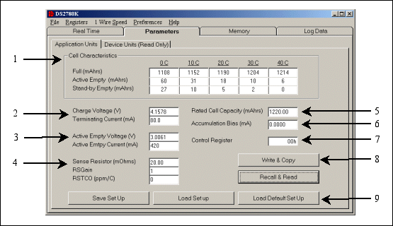
Figure 1. Application units subtab of parameters tab.
Cell Characteristics
The Full and Empty Levels are entered in mAmp-hours on the Application Units subtab. These cell characteristics are found by charging and discharging the cell under the conditions of the application over the temperature range from 0°C to 40°C. All these values are relative to the Stand-by Empty Level at 40°C, the lowest point, which will always be 0 mAmp-hours."Full" is defined as the capacity of the Li+ cell following a full charge at the specified temperature. "Active Empty" is defined as the point where the Active functions of the application will no longer operate. "Stand-by Empty" is the point where the application will lose power.
In a cell phone, for example, the Active Empty level would be defined as the point where there is not enough power to connect for a phone call. Below the Active Empty level calls cannot be made, but other phone functions, such as accessing the phone book or the calendar, are still possible. These functions can continue until the Stand-by Empty point is reached.
Prior to getting starting, the DS2780 must go through one Learn Cycle, meaning that the cell will need to go from the Active Empty point to the Full Charge point without interruption. When the Learn Cycle occurs, the DS2780 will adjust the Scalar value so that the full point matches the exact full point of the cell. The DS2780 can only modify the Scalar up to a maximum 100%. Starting with a best-case (largest possible) capacity of the cell is therefore recommended. This ensures that the DS2780 will be able to accurately adjust the Scalar without running into the maximum Scalar value.
If the cell characteristics are not known, a Dallas Semiconductor service can characterize the cells to be used in the application in an environment that simulates the charging and discharging profile of the application over temperature.
Charging Values
The DS2780 identifies a full charge based on the charge voltage (VCHG) and the terminating current (IMIN). A constant current/constant voltage method is often used to charge a Li+ cell, as shown in Figure 2. With this method, a cell is charged with a constant current until the cell's voltage reaches the constant voltage level. The charge is then switched to a constant voltage mode and the current will begin to taper off as the cell approaches a full charge. To identify a completed charge cycle, a charger will then look for the charging current to drop below a terminating current level.The DS2780 monitors voltage and current. When the real-time voltage is greater than the charge voltage and the charge current is positive and less than the terminating current, the DS2780 signals that a full charge has been reached. To make sure that the full point is detected, the DS2780 should be programmed with a charge voltage slightly below the actual charge voltage and a terminating current slightly above the actual terminating current. The charge voltage is entered in volts and the terminating current is entered in mAmps.
When a full charge is detected, several things happen. If the Learn Flag is set, a Learn Cycle takes place, which modifies the Age Scalar in order to accurately track the capacity of the cell. If the Learn Flag is not set, the Accumulated Current Register (ACR) is set to the Full Level based on the cell characteristics at the present temperature of the cell to correct any errors that may have been accumulated. The status of all flags can be viewed on the Fuel Gauge Data subtab of the Real Time tab, as shown by #4 in Figure 5.
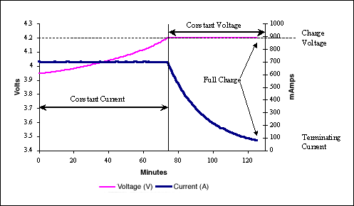
Figure 2. Typical constant current constant voltage charge profile.
Discharging Values
The DS2780 detects the device's active empty point when the real-time voltage falls below the Active Empty Voltage (VAE) and the current is greater than the Active Empty Current (IAE). To make sure that the active empty point is detected, the DS2780 should be programmed with an active empty voltage slightly above the actual empty voltage, and the active empty current slightly greater than the actual active current. The active empty voltage is entered in volts and the active empty current is entered in mAmps.When the active empty point is detected, the Active Empty Flag and the Learn Flag are set. To correct any errors that may have been accumulated, the ACR is set to the Active Empty Level based on the cell characteristics at the cell's present temperature. The Standby Empty Flag is set when the remaining standby relative capacity is less than 10%, as determined by the value of the ACR in comparison to the cell characteristics at the present temperature. The status of all flags can be viewed on the Fuel Gauge Data subtab of the Real Time tab, as shown by # 4 in Figure 6.
Sense Resistor Values
The value of the Sense Resistor (RSNSP) is entered in mΩ. This value is critical to accurate fuel gauge measurements because the DS2780 measures the voltage drop across the sense resistor and divides that voltage by the sense resistor value to calculate the current. The DS2780 supports sense resistor values from 3.922mΩ to 1Ω.The Sense Resistor Gain (RSGAIN) is an 11-bit value that can adjust the gain of the sense resistor from 0 to 1.999 in .001 steps. RSGAIN can be reprogrammed after module or pack manufacture to improve the current accuracy of the DS2780. This value is factory trimmed, so it should be modified with caution.
The Sense Resistor Temperature Compensation (RSTC) is an 8-bit value that sets the temperature coefficient of the sense resistor from 0 to 7782ppm/°C in 30.5ppm/°C steps. The user can disable the temperature compensation function by writing a 0 into the RSTC register. External resistor DS2780's will be shipped with 0 as the RSTC.
The user should program the RSGAIN and RSTCO registers cautiously. Copying the factory calibrations in Addresses 78h-7Ah to user EEPROM prior to changing these values is recommended. Using the Load Default Set Up button, described in the Saving and Loading Setups section below, will overwrite these values with a RSGAIN of 1.000 and a RSTCO of 0. To prevent accidental overwriting of the registers, the software will prompt the user any time those values have been modified.
Rated Cell Capacity
The Rated Cell Capacity is used to estimate the decrease in battery capacity that occurs in normal use. The value is entered in terms of mAmp-hours. Setting Rated Cell Capacity to the actual rated capacity sets the aging rate to approximately 2.4% per 100 cycles of equivalent full-capacity discharges. Partial discharge cycles are added to form equivalent full-capacity discharges. The default estimation results in 88% capacity after 500 equivalent cycles. The estimated aging rate can be adjusted by setting the Rated Cell Capacity to a different value from the cell manufacturer's rating. Setting the Rated Cell Capacity to a lower value accelerates the estimated aging. Setting the Rated Cell Capacity to a higher value retards the estimated aging.A 1000mAhr cell is used as an example. If 1000mAhr was stored as the Rated Cell Capacity, then the DS2780 would estimate the capacity after 500 cycles to be 880mAhr (88% of the original 1000mAhr capacity). If 1050mAhrs was stored as the Rated Cell Capacity, then the DS2780 would estimate the capacity after 500 cycles to be 924mAhr (92% of the original 1000mAhr capacity). If 950mAhrs was stored as the Rated Cell Capacity, then the DS2780 would estimate the capacity after 500 cycles to be 836mAhr (84% of the original 1000mAhr capacity).
Accumulation Bias Register
The Accumulation Bias Register can be used to estimate battery currents that do not flow through the sense resistor or battery self-discharge. The user can enter a positive or negative bias in mAmps, to be included in the current accumulation process. This value will not affect the current register, but will affect the ACR.Control Register
The value of the Control Register is stored in EEPROM to save values for the UVEN, PMOD, and RNAOP bits. These bits are described in the DS2780 data sheet.Accessing the DS2780
After the user has modified the values as described in Sections1 through 7, it is necessary to store the values to the DS2780. The Write & Copy button takes the values entered in the text boxes and converts them into the correct units that are stored in the DS2780. It then writes those values to the shadow RAM and then copies the values to EEPROM.The user should verify that the proper values were written to the device by left clicking on the Recall & Read button, which recalls the data from EEPROM and reads the data. It then displays the values as Device Units and Application Units on the appropriate subtab.
The actual values stored in the device can be viewed on the Device Units (Read-Only) subtab of the Parameters Tab, as shown in Figure 3, in both hexadecimal and device unit values.
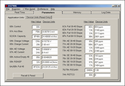
Figure 3. Device units subtab of parameters tab.
Saving And Loading Setups
There are three buttons at the bottom of the tab, as shown by #9 in Figure 1, that allow saving and loading of parameter setups. One button is the Load Default Set Up button which will load default data into all the text boxes on the tab. This data can be modified to fit the specific application or can be left as is unmodified for quick evaluation. Using the Load Default Set Up button only changes the values on the screen. To modify the memory of the DS2780, left-click on the Write & Copy button.If the user has modified the setup values, those values can be stored to a file using the Save Set Up button. Those values can later be loaded to the text boxes by using the Load Set Up button and choosing the desired file. Once again, to modify the memory of the DS2780, left-click on the Write & Copy button.
The user should program the RSGAIN and RSTC registers cautiously. Copying the factory calibrations in Addresses 78h-7Ah to user EEPROM prior to changing these values with the Load Set Up buttons, is recommended.
Estimate the ACR Level
Once the fuel gauge parameters are setup properly and written to the EEPROM of the DS2780, the next task is to estimate the cell's capacity by writing the value of the Accumulated Current Register (ACR). The user can use the voltage reading on the Parametric Data subtab of the Real Time tab, as shown by #1 in Figure 4, to estimate the ACR.If, for example, the voltage reading is greater than 4.0V, then set the ACR to 80% of the Full level. If the voltage is 3.6V, set the ACR to 50% of the Full level. If the voltage reading is at the Active Empty level, set the ACR to the Active Empty level. The Full and Empty levels at the present temperature can be viewed on the Fuel Gauge Data subtab of the Real Time Tab, as shown by #1 in Figure 6.
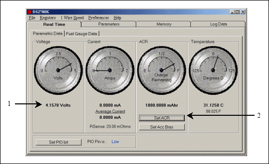
Figure 4. Parametric data subtab of the real time tab.
To set the ACR, left-click on the Set ACR button, as shown by #2 in Figure 4, which will bring up the Set Accumulated Current Register window in Figure 5. Then simply enter the estimated ACR value in mAmp-hours and left-click on the Write button. The user can left-click on the Read button to verify that the ACR was written properly. Then left-click on the Done button to close the Set Accumulated Current Register window.
This step is not required but allows for a rough capacity estimation before reaching a known point, such as a Full Charge or an Active Empty point. Until a known point is reached, either Full or Empty, there is no way of accurately knowing the remaining capacity of the Li+ cell.
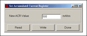
Figure 5. Set accumulated current register.
Start the Application and Learn the Capacity
After estimating the ACR, the DS2780K is ready to begin tracking the capacity of the Li+ in the application. To accurately estimate the total capacity available in the cell, the user should go through a Learn cycle with the DS2780 attached to the cell. Going through one Learn cycle allows the DS2780 to learn the actual capacity of the cell so the remaining capacity can be accurately tracked.To force a Learn cycle, discharge the cell to the Active Empty point as described in the Discharging Values section above. At that time, the Active Empty flag and Learn flag of the Status Register should be set, as shown by #4 in Figure 6. Then attach the application to the charger until a full charge is reached, as described in the Charging Values section above. At that time, the Full flag of the Status Register will be set and the DS2780 will learn the actual capacity of the cell.
The software will continually update the Parametric and Fuel Gauge Data subtabs of the Real Time tab with data from the DS2780. Simply continue charging and discharging the cell; the DS2780 will do the rest and the DS2780K will display the information.
Viewing the Fuel Gauge
The real-time fuel gauging data is displayed on the Fuel Gauge Data subtabs of the Real Time tab, as shown in Figure 6. The Full and Empty levels are displayed by #1 in Figure 6. Those values will change as the temperature reported by the DS2780 changes.The ACR will then track up and down between the full and empty levels, and the DS2780 will determine the remaining capacity relative to those levels. The various capacity values are displayed in #3 of Figure 6. The Remaining Active Absolute Capacity (RAAC) displays the difference in mAmp-hours from the present ACR reading and the Active Empty point at the present temperature. The Remaining Active Relative Capacity (RARC) is the percent of the total capacity of the Li+ cell available at the present temperature and remaining in the cell above the Active Empty level. The analog gauge, as shown by #2 in Figure 6, displays the RARC of the Li+ cell.
The Remaining Standby Absolute Capacity (RSAC) displays the difference in mAmp-hours from the present ACR reading and the Stand-by Empty point at the present temperature. The Remaining Stand-by Relative Capacity (RSRC) is the percent of the total capacity of the Li+ cell available at the present temperature and remaining in the cell above the Stand-by Empty point.
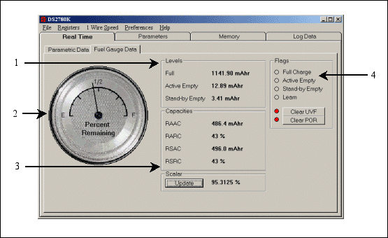
Figure 6. Fuel gauge data subtab of the real time tab.
 電子發(fā)燒友App






評論