Abstract: Using a temperature switch and fan driver IC along with a remote diode temperature switch provides thermal protection and simple fan drive functions for a system.
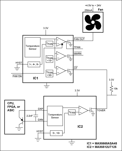
This 2-chip circuit provides fan control, over-temperature warning, and shutdown signals to prevent systems from being damaged by excessive heat. The circuit monitors the temperature of the circuit board and the die temperature of a CPU, FPGA, or other IC with an on-chip temperature-sensing transistor.
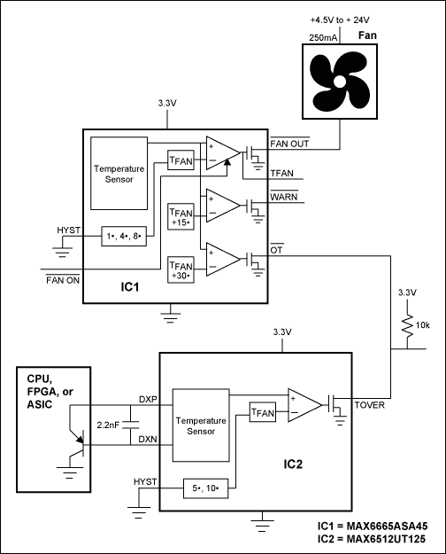
Figure 1.
IC1 is a temperature detector and fan driver for small (nominally 250mA) cooling fans. At low temperatures, the cooling fan is off, which minimizes noise and fan wear. When system temperature increases above 45°C, IC1's factory-programmed temperature comparator causes the Active-Low FANOUT fan drive pin to go active, pulling the fan's lower power supply terminal to ground and providing low-side drive to the fan. The fan can be rated for supply voltages up to 24V. After the fan is activated, the system temperature will normally either continue to increase (but at a slower rate) or will drop somewhat. If the temperature drops far enough, the fan will turn off. To avoid causing the fan to turn on and continuously, IC1 provides hysteresis of 1°C, 4°C, or 8°C, which can be set by the HYST pin.
If a thermal problem (such as higher-than-normal power dissipation or blocked ventilation paths) exists, system temperature may continue to increase. IC1 has two outputs that detect this condition. Active-Low WARN is activated when the temperature exceeds 60°C and the Active-Low OT output is activated when the temperature exceeds 75°C. Active-Low OT can be used as a system shutdown signal.
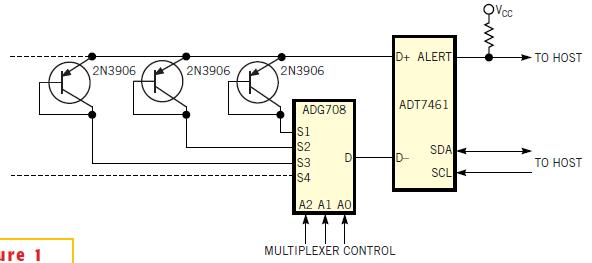
While IC1 monitors board temperature, IC2 monitors the die temperature of another chip - typically a CPU, FPGA, or ASIC. The target IC must have a small-signal p-n junction - usually a substrate PNP - available for temperature measurement purposes. IC2 forces currents through the sense junction, measures the resulting voltages, and calculates the temperature of the junction. This temperature is compared against a preset threshold. When the junction temperature exceeds the threshold (125°C in this case), IC2's output pin goes active and can be used to shut the system down. The open-drain shutdown outputs of IC1 and IC2 are connected to a common pull-up resistor and to the power-supply's shutdown terminal. If either the board temperature or the chip temperature exceeds the maximum safe rating, the system shuts down before damage can occur.
IC1 should be in a location that allows it to measure the temperature of interest. Depending on the system, this could be near a "hot spot"or in the cooling fan's airflow path. The traces between IC2 and the remote sense junction should be reasonably short and separated from high-speed data traces.
A similar version of this article appeared in the November 8, 2001 issue of EDN magazine.
This 2-chip circuit provides fan control, over-temperature warning, and shutdown signals to prevent systems from being damaged by excessive heat. The circuit monitors the temperature of the circuit board and the die temperature of a CPU, FPGA, or other IC with an on-chip temperature-sensing transistor.

Figure 1.
IC1 is a temperature detector and fan driver for small (nominally 250mA) cooling fans. At low temperatures, the cooling fan is off, which minimizes noise and fan wear. When system temperature increases above 45°C, IC1's factory-programmed temperature comparator causes the Active-Low FANOUT fan drive pin to go active, pulling the fan's lower power supply terminal to ground and providing low-side drive to the fan. The fan can be rated for supply voltages up to 24V. After the fan is activated, the system temperature will normally either continue to increase (but at a slower rate) or will drop somewhat. If the temperature drops far enough, the fan will turn off. To avoid causing the fan to turn on and continuously, IC1 provides hysteresis of 1°C, 4°C, or 8°C, which can be set by the HYST pin.
If a thermal problem (such as higher-than-normal power dissipation or blocked ventilation paths) exists, system temperature may continue to increase. IC1 has two outputs that detect this condition. Active-Low WARN is activated when the temperature exceeds 60°C and the Active-Low OT output is activated when the temperature exceeds 75°C. Active-Low OT can be used as a system shutdown signal.
While IC1 monitors board temperature, IC2 monitors the die temperature of another chip - typically a CPU, FPGA, or ASIC. The target IC must have a small-signal p-n junction - usually a substrate PNP - available for temperature measurement purposes. IC2 forces currents through the sense junction, measures the resulting voltages, and calculates the temperature of the junction. This temperature is compared against a preset threshold. When the junction temperature exceeds the threshold (125°C in this case), IC2's output pin goes active and can be used to shut the system down. The open-drain shutdown outputs of IC1 and IC2 are connected to a common pull-up resistor and to the power-supply's shutdown terminal. If either the board temperature or the chip temperature exceeds the maximum safe rating, the system shuts down before damage can occur.
IC1 should be in a location that allows it to measure the temperature of interest. Depending on the system, this could be near a "hot spot"or in the cooling fan's airflow path. The traces between IC2 and the remote sense junction should be reasonably short and separated from high-speed data traces.
A similar version of this article appeared in the November 8, 2001 issue of EDN magazine.
 電子發(fā)燒友App















評論