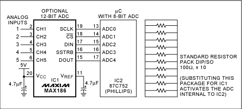
現(xiàn)在很多單片機都有ADC功能了,10位或者12位的�����,使用ADC測量電壓是很方便的���,測量電阻阻值的話可以使用歐姆定律進行分壓然后測量分壓后的電壓即可計算出電阻阻值��,最簡單的電阻測量電路如下圖:
2019-07-08 07:58:34
MSP430系列MCU的ADC有10位���,12位�����,分辨率我知道是12位更高�,但是采樣的精度都是同樣的可靠嗎�,我用過這兩中ADC采集同一個電平信號,10位的采集結果顯示波動更大�����。是不是12位ADC比10位的性能更好����,不僅僅體現(xiàn)在分辨率?
2015-03-10 16:08:35
1μs的雙12位ADC是什么意思,初學者�,請多多指教
2018-05-23 16:50:18
采用LTC2360ITS8,100KSPS單極性,單通道����,12位,SPI兼容串行ADC的演示板采用6引腳或8引腳TSOT封裝
2019-04-28 10:26:57
采用LTC2361ITS8,250KSPS的演示板���,這些單極性�����,單通道�����,12位���,SPI兼容串行ADC提供6引腳或8引腳TSOT封裝
2019-04-28 10:30:52
DC1190A-A����,LTC2366演示板�,12位��,3Msps SAR ADC�。采用LTC2366ITS8,3MSPS的演示板����,這些單極性,單通道�����,12位����,SPI兼容串行ADC提供6引腳或8引腳TSOT封裝
2019-04-26 09:23:14
DN192-12位3Msps SAR ADC解決了管道問題
2019-08-06 14:18:32
1、12位ADC是一種逐次逼近型模擬數(shù)字轉(zhuǎn)換器�����。它有多達18個通道�,可測量16個外部和2個內(nèi)部信號源。各通道的A/D轉(zhuǎn)換可以單次�、連續(xù)、掃描或間斷模式執(zhí)行�����。ADC的結果可以左對齊或右對齊方式存儲在
2021-08-05 06:53:44
12位ADC是什么?12位ADC有幾種轉(zhuǎn)換模式呢�����?
2021-10-29 08:07:32
(Teledyne LeCroy)采用了12位ADC的示波器���,其信號分辨能力是傳統(tǒng)8位示波器的16倍���,有望帶來中低端示波器領域的技術革命。新產(chǎn)品包括HDO4000和HDO6000兩個系列�����,采用力科最新的HD4096
2019-06-10 08:13:51
一���、12位逐次逼近型ADC轉(zhuǎn)換原理ADC中輸入的模擬信號是連續(xù)的�,而輸出的數(shù)字信號是離散的�����,所以轉(zhuǎn)換時必須對輸入的模擬信號進行采樣��;然后再把采樣值轉(zhuǎn)換成為輸出的數(shù)字信號;這個過程需要經(jīng)過采樣��、保持
2022-02-25 06:54:14
適用于高帶寬��,高采樣率應用程序的新型DESCLKI??Q模式與ADC10D1x00�����,ADC12D1x00引腳兼容用于多芯片同步的自動同步功能內(nèi)部端接���,緩沖差分模擬輸入交錯定時自動和手動偏斜調(diào)整用于系統(tǒng)調(diào)試
2021-01-08 09:15:08
適用于高帶寬,高采樣率應用程序的新型DESCLKI??Q模式與ADC10D1x00�����,ADC12D1x00引腳兼容用于多芯片同步的自動同步功能內(nèi)部端接�����,緩沖差分模擬輸入交錯定時自動和手動偏斜調(diào)整用于系統(tǒng)調(diào)試
2021-01-08 09:15:08
ADC12D1600RFIUT/NOPB 訂貨***黃小姐微信同號 12 位�、2.0/3.2 GSPS 射頻采樣 ADCThe 12-bit 3.2- and 2-GSPS
2018-07-30 07:21:58
144FCBGAADC12D800RFIUT/NOPB詳細參數(shù)IC ADC 12BIT FOLD INTERP 292BGAADC08DJ3200AAV詳細參數(shù)IC ADC 8BIT FOLD INTERP
2020-07-13 11:46:38
的 ADC 產(chǎn)品系列通過一系列封裝選項為工業(yè)、汽車�、醫(yī)療���、通信、企業(yè)和個人電子產(chǎn)品應用提供采樣速度高達 10.4GSPS 的高速器件和分辨率高達 32 位的精密器件�����。 分辨率? < 12 位
2020-06-01 18:29:26
undecimated 12- and 8-bit ADC output), which features a JESD204B interface. The EVM has
2018-08-03 07:46:44
INTERP 144FCBGAADC12D800RFIUT/NOPB詳細參數(shù)IC ADC 12BIT FOLD INTERP 292BGAADC08DJ3200AAV詳細參數(shù)IC ADC 8BIT
2020-07-13 11:45:09
ADC12J2700EVM的描述ADC12J2700EVM是一個評估模塊(EVM)����,允許對德州儀器的ADC12J2700進行評估。ADC12J2700是一款低功耗�����、12位���、2.7-GSPS射頻采樣
2020-04-09 09:44:08
ADC12_many_cover_Init(void){//unsigned int i;P6SEL|=0X08;//使能AD通道A3ADC12CTL0=ADC12ON+SHT0_8+MSC;//打開
2019-03-25 04:15:05
;=~(BIT0+BIT1);P6SEL |= BIT0+BIT1;// 使能ADC通道ADC12CTL0 = ADC12ON+SHT0_8+MSC;// ADC12ON打開ADC�����,//SHT0_8設置
2013-07-08 20:38:28
48VQFNADC34J45IRGZT詳細參數(shù)IC ADC 14BIT PIPELINED 48VQFNADS5271IPFP詳細參數(shù)IC ADC 12BIT PIPELINED 80HTQFPADS5444IPFP
2020-09-04 10:27:30
ADC介紹12位ADC是一種逐次逼近型模擬數(shù)字轉(zhuǎn)換器�����。它有多達18個通道���,可測量16個外部和2個內(nèi)部信號源����。各通道的A/D轉(zhuǎn)換可以單次�����、連續(xù)���、掃描或間斷模式執(zhí)行。ADC的結果可以左對齊或右對齊方式
2021-08-05 06:29:51
1��、 ADC簡介STM32F103系列有3個ADC����,精度為12位,ADC是一個逐次逼近型模擬數(shù)字轉(zhuǎn)換器�,且每個ADC有18個通道,可以測量16個外部和2個內(nèi)部信號源���,每個通道的A/D轉(zhuǎn)換可以進行單次
2021-08-02 07:27:52
ADC是多少位的��?12位ADC有多少個����?1個、2個或多至3個�,視不同的器件而不同;每個又有多個通道���。關于通道的名堂:10.3.3 通道選擇 有16個多路通道����??梢园艳D(zhuǎn)換分成兩組:規(guī)則的和注入的。在任意多個通道上以任意順序進行的一系列轉(zhuǎn)換構成成組轉(zhuǎn)換���。例如���,可以如下...
2021-08-05 06:21:17
嗨,大家好�,我有一些問題,使用ADC和輸出的結果在I2C使用CY8CKIT-042-BLE����,將非常感謝您的幫助,請!我試圖發(fā)送12位ADC輸出超過I2C�����,并設立了一個6電阻分壓器���,以幫助我了解不同產(chǎn)
2018-12-10 15:45:37
問題一:AD9949內(nèi)部的12高性能位ADC是什么類型的���,如逐次逼近型、Sigma-Delta型等����;
問題二:AD9949中提到了很多的增益調(diào)整���,我有點搞暈了�����,比如我的輸入信號是1Vp-p�����,經(jīng)過
2023-12-25 07:45:00
C8051F007單片機內(nèi)部的12位ADC �����,如何提高精度���?
2023-10-16 14:04:26
C8051F007單片機內(nèi)部的12位ADC �,如何提高精度���?
2023-10-17 08:11:58
CC2530內(nèi)部ADC是12位的還是14位的�����,如果是12位的為何寄存器是14位的��。
2018-06-24 03:23:12
CC2530 內(nèi)部ADC是12位的還是14位的���,如果是12位的���,為何寄存器是14位的。
2018-06-24 06:23:40
看了CC2530的中文手冊�,上面寫道最高ADC位數(shù)是12位,然而在協(xié)議棧里可以看到抽取率可以選14位�。通俗一點說,CC2530最高的12位ADC采集數(shù)據(jù)時���,是將數(shù)據(jù)精分成2的12次方=4096份�����,還是分成2的11次方=2048份�?這里有一個有效位的概念����,我沒有弄清楚���,大家思考過嗎��?
2017-02-22 19:41:59
DMA向?qū)Р辉试S將8位SAR ADC連接到8位VDAC��。它抱怨不兼容的突發(fā)大小�。具體的錯誤是“所選的源和目的地具有不兼容的突發(fā)大小。不能選擇有效的大小���。附上一個包含三個相關組件的最小示例項目����。這足以
2018-12-21 15:06:54
您好��,這是我在Microchip論壇上的第一篇文章����,我非常感謝大家的幫助。我目前使用的是DSPIC33 EP512MC204微控制器����,我在ADC功能方面遇到了一些問題。我配置它是在12位模式���,但轉(zhuǎn)換
2018-12-13 16:38:37
使用DMA方式實現(xiàn)ADC 8位精度采樣AT32 部分型號不支持ADC 精度調(diào)整����,固定以12 位精度進行采樣轉(zhuǎn)換。當應用期望使用8 位精度數(shù)據(jù)時����,按照常規(guī)用法將無法滿足。此時應如何處理����?
2023-10-23 06:23:44
G6RL1ADC12
2023-03-28 14:54:08
LPC176x/175x 12位ADC設計指南
2022-12-07 07:40:31
LTC2355-12 / LTC2355-14的典型應用是具有差分輸入的12位/ 14位,3.5Msps串行ADC
2019-04-29 08:32:50
我正在使用 S32K344s ADC。網(wǎng)站上的數(shù)據(jù)表和規(guī)范聲明了 12 位分辨率���,但 ADC 外設可以在 CALBISTREG 寄存器中設置為 14 位分辨率�。
如果 ADC 指定為 12 位��,14 位分辨率和 12 位分辨率之間有什么區(qū)別���?
2023-06-06 09:10:56
DN138-SO-8中的微功率ADC和DAC為PC提供12位模擬接口
2019-07-12 11:08:39
STC12系列單片機的ADC采樣是多少位的
2023-10-16 07:39:55
STM32F407的12位ADC是什么?有何功能�?
2022-01-25 07:08:46
STM32的ADC模塊,請允許我用如此通俗的語言:普通話來介紹STM32ADC模塊的特色1��、1MHz轉(zhuǎn)換速率��、12位轉(zhuǎn)換結果(12位���、記住這個12位哈����、因為2^12=4096 �,也請記住4096哈
2015-02-12 14:51:09
STM8的ADC精度是多少位的
2023-10-27 07:38:14
N76E003的分辨率是12位���,
value= (ADCRH<<4) + ADCRL;//得到ADC轉(zhuǎn)換值
ADCRH是高8位�����,這個例文件向左移4位+ADCRL的低4位���,這個是8位分辨率還是10位,如果要使用12位是不是���,直接ADCRH+ADCRL就可以�。
2023-06-19 06:02:25
一:ADC以及u8g2介紹105有12位的ADC,ADC通道共有7個���,其中ADC通道0����,采集內(nèi)部電壓����。這里我們利用ADC0采集電壓,并在OLED屏幕上顯示�����。U8g2:一個是嵌入式設備的單色圖形庫
2022-06-05 18:16:26
DN159- 新的14位����,800ksps ADC升級12位系統(tǒng),具有81.5dB SINAD��,95dB SFDR
2019-05-28 14:17:21
最新剛出來的高速ADC芯片����,MXT2021替代ADC12D1000MXT2021產(chǎn)品手冊.rar (2.36 MB )
2019-07-05 04:36:10
大家好,你們中有人嘗試使用AD1CON2寄存器中的OFACK位校準12bit ADC嗎�?12位ADC數(shù)據(jù)表沒有多少說明。第一個附件����。當試圖獲得ADC偏移量時��,我總是測量設置為CHCH0SA的內(nèi)容
2019-10-30 10:49:39
STM32 MCU 具有 12 位 ADC 分辨率�,但一些 MCU 聲稱“高達 16 位硬件過采樣”。當我在 STMCubeMX 中設置 ADC 時���,沒有“硬件過采樣”選項���,如何實現(xiàn) 16 位 ADC 分辨率?
2022-12-01 06:11:00
我在論壇上看到了很多基于51的��,大多數(shù)是八位的adc��,msp430的adc是12位的���。該怎么改那些八位的?���?����?,他們在和計算機通信時�����,發(fā)送的八位數(shù)就是adc的轉(zhuǎn)換結果嗎�?
2012-10-14 17:59:00
親愛的大家�����,我的問題是如何通過LVDS將ADC AFE 5804 12位http://www.ti.com/product/afe5804連接到Spartan 3E入門套件����。首先,我想模擬知道ADC
2019-07-10 08:19:23
如果將ADC設置為12位其獲得的ADC值代表什么��?求解答
2023-01-06 08:39:30
我使用帶有12位ADC的STM32F303來使用ADC本身讀取輸出電壓。據(jù)我所知��,ADC的Vref與器件的VDD相同�。對嗎?但是��,當將微控制器的VDD引腳輸出饋送到ADC時�����,它給出的值為4043而不是4096.在我的情況下這樣的誤差是否正常�?謝謝你們�����。
2018-09-04 09:49:02
DN463 - 將您的微控制器 ADC 升級至真正的 12 位性能
2019-09-16 08:21:22
我想讀一讀從LTC2309到I2C的12位ADC轉(zhuǎn)換����,從PIC18F46K80��。有人有樣本代碼或嘗試過類似的使用MCC生成的代碼�����?謝謝爾維奧
2020-03-18 08:32:57
轉(zhuǎn)換,這些都是對小幅度信號測量精度要求較高的例子?��?紤]到所有這些測試場景�����,全新4系列MSO的核心是12位模數(shù)轉(zhuǎn)換器(ADC)���,它提供的垂直分辨率是傳統(tǒng)8位ADC的16倍。與一些示波器供應商不同�,它們
2020-02-13 10:14:35
問題一:AD9949內(nèi)部的12高性能位ADC是什么類型的,如逐次逼近型�、Sigma-Delta型等;問題二:AD9949中提到了很多的增益調(diào)整���,我有點搞暈了���,比如我的輸入信號是1Vp-p,經(jīng)過
2018-11-14 11:03:56
您好�����, 請問有采樣率250MHz左右 分辨率為12位�����,管腳兼容8位分辨率的adc嗎�? 謝謝�����!
2019-02-22 11:53:35
您好��,
請問有采樣率250MHz左右 分辨率為12位����,管腳兼容8位分辨率的adc嗎?
謝謝��!
2023-11-21 06:46:46
本帖最后由 sosgood 于 2017-2-20 12:36 編輯
請問��,誰手里有16位或者12位 8通道或者4通道 差分輸入ADC的芯片資料�,或者提供芯片型號,謝謝了?�。���?��!
2017-02-20 11:58:08
北京 - 凌力爾特公司 (Linear Technology Corporation) 推出一系列引腳和軟件都兼容的 16 位和 12 位 SAR ADC,這個系列的器件保證在 -40oC 至
2018-11-26 10:51:18
)4.YA14D250:14位250MHz雙通道A/D轉(zhuǎn)換器(=AD9643)5.MXT2088直接替代AD9288(100M)分辨率雙8bit的 ,6.MXT2002直接替代ADC08D500 (500M)分辨率雙
2013-09-06 11:29:07
The ADC12030, and ADC12H030 families are 12-bit plus signsuccessive approximation Analog-to-Digital
2009-10-10 10:48:44 12
12 The ADC12130, ADC12132 and ADC12138 are 12-bit plussign successive approximation Analog-to-Digital
2009-10-12 09:07:44 16
16 ADC12D1000
2010-05-27 15:55:46 17
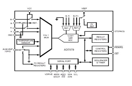
17 AD7879 內(nèi)建12 bit ADC可支持4線式的觸控屏幕
產(chǎn)品規(guī)格 .Supply Power Voltage ─ 2.7~3.6V .Touch screen
2010-01-08 16:37:02 909
909 
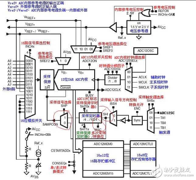
ADC12_A模塊是一個高效的12位模數(shù)轉(zhuǎn)換器���。本章節(jié)將主要介紹MSP430 5XX單片機的ADC12_A模塊���。
2011-12-08 17:35:10 0
0 ADC12是一個多源中斷:有18個中斷標志(ADC12IFG.0~ADC12IFG.15與ADC12TOV�����,ADC12OV)�,但只有一個中斷向量�。所以需要 設置這18個標志的優(yōu)先級順序,按照優(yōu)先級順序安排中斷標志的響應���,高優(yōu)先級的請求可以中斷正在服務的低優(yōu)先級��。
2018-04-10 17:55:02 9752
9752 
msp430內(nèi)部含有 ADC12模塊�,可以完成12位的模數(shù)轉(zhuǎn)換�,當對精度或其他指標要求不高時�����,可以選用430單片機內(nèi)部的 ADC12完成模數(shù)轉(zhuǎn)換工作�。
2018-05-04 09:40:17 6
6 電子發(fā)燒友網(wǎng)為你提供TI(ti)ADC12D1600QML-SP相關產(chǎn)品參數(shù)�����、數(shù)據(jù)手冊,更有ADC12D1600QML-SP的引腳圖����、接線圖、封裝手冊����、中文資料、英文資料���,ADC12D1600QML-SP真值表�����,ADC12D1600QML-SP管腳等資料��,希望可以幫助到廣大的電子工程師們�。
2018-11-02 19:01:06

14/12位1.8V單ADC
2021-04-23 18:44:13 11
11 ADC824 Microcomporter����,24位ADC���,16位ADC�,12位DAC����,F(xiàn)lash MCU數(shù)據(jù)Sheet
2021-06-18 13:00:31 13
13 IP_數(shù)據(jù)表(A-12):12bit 2MSps SAR ADC
2023-03-16 19:33:26 0
0 ADC12DJ3200EVM 供應商 ADC12DJ3200EVM怎么訂貨 ADC12DJ3200EVM 價格
2021-12-22 16:23:41 474
474 
IP_數(shù)據(jù)表(A-12):12bit 2MSps SAR ADC
2023-07-06 20:19:44 0
0 電子發(fā)燒友網(wǎng)為你提供ADI(ADI)AD7927: 8-Channel, 200 kSPS, 12-Bit ADC with Sequencer in 20-Lead TSSOP Data
2023-10-12 18:50:13

電子發(fā)燒友網(wǎng)站提供《對12Bit A/D轉(zhuǎn)換器(ADC12)的更正和RA2組用戶手冊.pdf》資料免費下載
2024-02-19 10:51:35 0
0

 電子發(fā)燒友App


評論