The RS-485 standard was developed jointly by two trade associations: the Electronic Industries Association (EIA) and the Telecommunications Industry Association (TIA). The EIA once labeled all its standards with the prefix "RS" (Recommended Standard). Many engineers continue to use this designation, but the EIA/TIA has officially replaced "RS" with "EIA/TIA" to help identify the origin of its standards. Today, various extensions of the RS-485 standard accommodate a large variety of applications.
The RS-485 and RS-422 standards share many of the same attributes, and are often confused for that reason. The table below compares the different standards. The RS-485, which specifies bi-directional and half-duplex data transmission, is the only EIA/TIA standard that allows multiple receivers and drivers in "bus" configurations. Conversely RS-422 EIA/TIA standard specifies a single, unidirectional driver with multiple receivers. Therefore RS-485 parts are backward compatible and interchangeable with their RS-422 counterparts. However, RS-422 drivers should not be used in an RS-485 system for they cannot relinquish control of the bus.
RS-485 and RS-422 Standards
| ? | RS-422 | RS-485 | PROFIBUS |
| Mode of operation | Differential Unidirectional Multipoint |
Differential Full Duplex Multipoint |
Differential Full Duplex Multipoint |
| Allowed no. of Tx and Rx | 1 Tx, 10 Rx | 32 Tx, 32 Rx | 32 Tx, 32 Rx |
| Maximum cable length | 4000ft length | 4000ft length | 4000ft length |
| Maximum data rate | 10Mbps | 10Mbps | 40Mbps |
| Minimum driver output range | ±2V | ±1.5V | ±2.1V |
| Maximum driver output range | ±5V | ±5V | ±5V |
| Maximum driver short-circuit current | 150mA | 250mA | 250mA |
| Tx load impedance | 100Ω | 54Ω | 54Ω |
| Rx input sensitivity | ±200mV | ±200mV | ±200mV |
| Maximum Rx input resistance | 4kΩ | 12kΩ | 12kΩ |
| Rx input voltage range | ±7V | -7V to +12V | -7V to +12V |
| Rx logic high | >200mV | >200mV | >200mV |
| Rx logic low | <200mV | <200mV | <200mV |
PROFIBUS
PROFIBUS is a communication standard built upon an RS-485 type transceiver. It is intended for industrial control networks. The PROFIBUS specification covers the software protocol, the connector type, and a differential termination network.ESD Protection
The differential signal paths of RS-485 and RS-422 systems provide reliable data transmission in the presence of noise and are also capable of rejecting large common-mode voltages. To guard against the much higher voltage levels associated with electrostatic discharge (ESD), a different class of protection is needed.The charged capacitance of a human body enables a person to destroy integrated circuits with a single touch. Such a contact can easily occur during the installation of an interface cable. To prevent ESD damage, Maxim's interface ICs incorporate "ESD structures." The ESD structures protect the transmitter outputs, receiver inputs, digital interface connections, and analog connections to the RS-422/RS-485 transceivers against ESD levels up to ±15kV.
Maxim guarantees the specified ESD protection by repeatedly testing the IC terminals in 200V increments to verify a sequence of levels up to ±15kV. Devices with this rating (per the Human Body Model or the IEC 1000-4-2 specification) are designated by an additional "E" suffix on the part number. For more information on ESD protection, refer to the application note titled "Maxim Leads the Way in ESD Protection".
Data Rates and Driver Loading
The load presented to an RS-485/RS-422 driver is quantified in terms of the unit load, which is defined as the input impedance for one standard RS-485 receiver (12kΩ). Thus, a standard RS-485 driver is capable of driving 32 unit loads (32 12kΩ loads in parallel) or 375Ω. The input impedance for certain RS-485 receivers is 48kΩ (1/4 unit load) or even 96kΩ (1/8 unit load), and as many as 128 or 256 respective receivers, can be connected to a single RS-485 bus. Any combination of receiver types can be connected together, provided their parallel impedance does not exceed 32 unit loads (RLoad > 375Ω).Consequences of High Data Rates
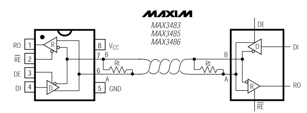
Faster transmissions require higher slew rates at the driver output, and higher slew rates produce higher levels of electromagnetic interference (EMI). Some RS-485 transceivers minimize EMI by limiting their slew rates. Lower slew rates also help to control the reflections caused by fast transitions, high data rates, or long cables. Essential for minimizing reflections are termination resistors that match the cable's characteristic impedance. Common RS-485 cables (a twisted pair of 24AWG wires) should be terminated with a 120Ω resistor at both ends.For more about RS-485 designs, refer to Methods for Trimming the Power Required in RS-485 Systems and Selecting and Using RS-232, RS-422, and RS-485 Serial Data Standards.
 電子發(fā)燒友App










評(píng)論