Abstract: Digital potentiometers (pots) offer advantages in volume control applications over bulky mechanical pots, especially in handheld portable devices such as MP3 players, PDAs, cell phones, or stereo AM/FM radios. This document describes the types of digital pots available in audio volume control such as logarithmic taper pots (log pots). It also discusses several common designs using log taper pots and audio amplifiers, their advantages and disadvantages, and circuit recommendations.
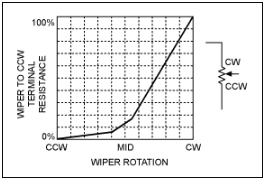
Historically audio volume controls used a special kind of potentiometer with a 'log' (or sometimes 'audio') taper or law (see below). This derives from the roughly logarithmic response of the ear to changes in sound pressure levels.
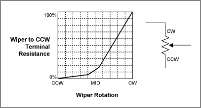
Figure 1.
In general, the result is that the mid-point of the rotation usually gives around 20dB attenuation of the audio signal, giving rapidly increasing attenuation from the mid-point counter-clock wise (CCW), and finer control over the 'louder' settings from the mid-point clock wise (CW).
While this works well, there are a number of reasons not to use a pot in a small portable device, space constraints and reliability issues being just two. Use of up/down buttons in conjunction with some form of host processor is a common volume control interface for modern devices, providing a cheap, useable solution instead of using of a bulky mechanical pot.
Stereo (or ganged) rotary pots have a mechanical tracking issue also, in that mechanical tolerances means L-R tracking suffers as the volume is adjusted. Also, the desired transfer function should be considered — is full attenuation desired, or rather a gain trim control offering (say) 30dB of adjustment range, but no 'fully off' position?
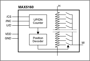
Figure 2.
The most commonly available types are effectively 'linear' pots, meaning that their resistive increments are equally weighted. A reasonably constant 'dB-per-step' law is desirable in an audio volume control, so the design may have to emulate this 'log' behaviour in some way - we are no longer constrained by the mechanical potentiometer 'audio' taper. A second issue is that while the digital pot steps are usually designed to give equal value resistive increments, a by-product of the process variation is that the total end-to-end resistance varies widely from part to part - as much as ±30% in some types. This must be taken into account when designing a circuit requiring close matching between 2 channels using separate digital pots. A further requirement is the transitions should be as glitch free as possible, so a make-before-break wiper arrangement should be considered mandatory.
The circuit in Figure 3 would seem to give adequate results. Using two MAX5160L's (assuming their digital inputs are suitably controlled) around a MAX4252, the circuit should give evenly tracking gain or attenuation over a nominal ±6dB range. The circuit should work over a VCC range from 2.7V to 5V, have 32 useable gain settings and even the power on reset state of the MAX5160L gives (approximately) a unity gain setting. The drawback to this implementation is the ±25% overall resistance variation of the digital pot. This could lead to a wide gain tolerance, especially on the settings at the extremities of resistance, channel-to-channel as well as unit-to-unit. For example, assuming the 50K resistors are ±1%, then the nominal, maximum +6dB setting could vary between limits of: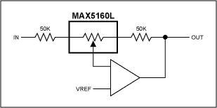
Figure 3. ±6db stereo gain trim control, 32 gain settings (1 channel shown).
This amount of left-right mismatch is easily audible. This circuit can be made to work by selecting or trimming the support resistors (or selecting the digital pot!) to suit, but this is not feasible in mass production. A design approach must be found which minimizes or eliminates this gain error.
The circuit in Figure 4 uses the MAX5160L digital pot in a divider chain supplying the MAX4252 op amp with some positive feedback in addition to the usual negative feedback via the 100K and 50K resistors. The gain of this circuit can be shown to be:
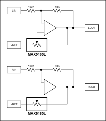
Figure 4. ±6dB stereo gain trim control, 17 gain settings, improved design.
When the MAX5160L wiper is positioned at the VREF terminal, the gain of the circuit is -0.5V/V, as there is no positive feedback contribution. When the wiper is at mid scale, Kp = 0.5, and the gain is now -2V/V. Hence, by using those 17 positions between VREF and midscale the gain can be varied over a ±6dB range. The 15 unused positions have been traded off for repeatability, as the gain value does not depend upon the digital pot resistance tolerance, as did the circuit of Figure 1. The gain tolerance is now only limited by the ±1% 100K/50K resistors, and the INL/DNL error of the MAX5160L (±4.6% max.).
An interesting point to note, the limit for stability in this circuit is reached when Kp ≥ 2/3, when the positive feedback fraction meets or exceeds the negative. The host processor controlling the MAX5160L should therefore prevent this situation occurring.
The circuit in Figure 5 shows an obvious appraoch to a 'traditional' style volume control using digital pots. All codes are valid, with settings ranging from 0dB to full attenuation. Table 1 shows the calculated attenuations based on the MAX5160L's 32 steps.
Table 1. Calculated Results of Figure 3 Circuit
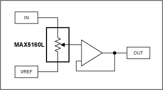
Figure 5. Traditional volume control (1 channel shown), has drawbacks.
Notice how the attenuation figures are spread. There is less than 6dB total variation over the first 15 codes, less than 1dB over the first four, not particularly useful. Interestingly, even when choosing a part with a far larger number of taps, you still only get 6dB variation over half of the codes.
One approach sometimes used is to pick a subset of the codes available to get a reasonably constant 'dB/step figure'. For instance, using only those codes highlighted in Table 1 gives roughly 3dB/step, allowing 11 settings. This can work well if the digital pot chosen has many tap positions (256 or higher). However, these parts are generally more expensive and given that the majority of the tap positions will not be used (unless, perhaps, when interpolating between volume settings), it would seem more efficient to try and utilize more of the existing taps by using a different topology.
Resistively loading the wiper of a linear pot to 'bend' the characteristic is an old trick, usually the load resistor being about 1/20th the value of the linear pot resistance. The two disadvantages of applying this with a 'linear' digital pot is that the input impedance of the pot is now dependant on gain setting (lowest at max.volume), and (again) the wide tolerance on end-to-end resistance means L-R tracking suffers at any setting apart from the extremes. The drawing below shows the idea:
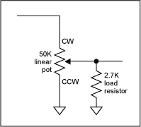
Figure 6.
The circuit of Figure 7 yields a traditional volume control characteristic, much like that of Figure 5. However, it uses a little positive feedback to even out the step sizes to roughly 1.6dB/step over most of its useable range. One immediate disadvantage is that the negative feedback fraction (Kn) has to be 0.5 or higher for this to yield usable results (although 0.25 would be the limit of stability), meaning we have already thrown away around half the available codes in order for the circuit to operate. However, the remaining 17 codes are all used (no gaps as in the Figure 6 example), as indicated in Table 2 below. The third column shows the delta in step sizes, showing how consistent they are over the majority of the attenuation range - Figure 8 shows the linearising effect, with gain in dB on the Y-axis, plotted against tap number on the X-axis. This compares favorably with the circuit of Figure 6, where the highlighted values gave roughly 3dB steps and only 11 settings.
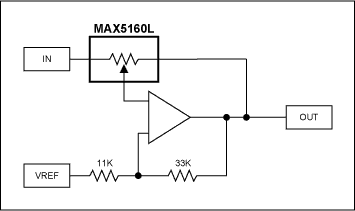
Figure 7. Near-constant Db/step topology (1 channel shown), improved design.
One side effect of the topology (with the values shown) is that there will be a 6dB boost for the midscale value of the digital pot. This can often be accommodated in the gain structure of the full audio path, where some gain shifting is usually inevitable.
Table 2. Calculated Results of Figure 7 Circuit
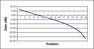
Figure 8. Stereo, cascaded traditional volume control, more = better?
The circuit of Figure 9 uses a total of 4 MAX5160L's to produce a high resolution, stereo volume control. The number of possible valid codes per channel is greatly increased, giving 32 x 32 or 1024 attenuation codes. Again, the end-to-end resistance tolerance does not have any first order effect (due to the buffering between the two digital pot stages), L-R tracking is only limited by the tap-to-tap matching accuracy. The wiper resistance has little loading effect as each wiper sees a high impedance op amp input.
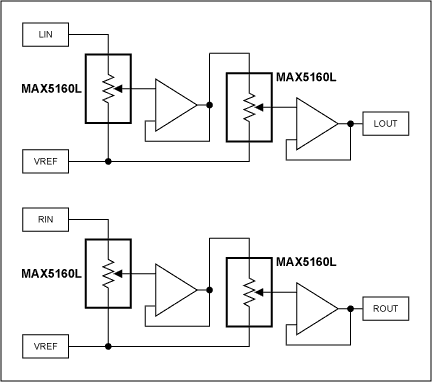
Figure 9.
Of the 1024 codes, some of them give duplicate attenuation values (for example: first pot is at -6dB, second is fully up, gives -6dB overall. Same as first pot fully up and second at -6dB), plus if either pot is set to full attenuation, any setting on the other pot is irrelevant, all of which leaves something like 348 unique attenuation settings from 0 to -60dB (actually -59.66dB). To map the codes to an attenuation figure, some sort of simulation or spreadsheet approach would seem appropriate. The graph below shows the spread of attenuation obtained, including duplicate values:
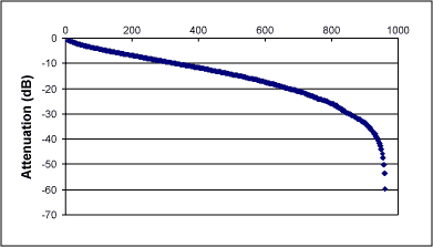
Figure 10.
Figure 10 shows that most of the codes give attenuation values between 0 and -40dB. The 'delta', or dB step size between each attenuation value can be plotted in a similar manner to that in Table 2, to give a visual indication of the granularity of the steps:
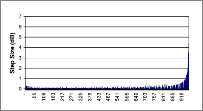
Figure 11.
The granularity of the steps appears very evenly distributed, with differences in most of the steps being well under 0.5dB, only reaching 1dB at -41.6dB, with the penultimate 6dB step between -53.6 and -59.6. Repeated codes appear on the graph as 'zero' delta figures. This yields the kind of control range and granularity required in the most exacting pro-audio level controls.
There are, however, limitations to this approach. Obviously, this circuit has a reasonable control overhead (perhaps using look up tables to retrieve values and using some kind of ranging algorithm to obtain smooth volume transitions), but unlike the circuit in Figure 4, there is no conditional stability situation, so any combination of codes is fine. More seriously, variations in the tap-to-tap resistor matching between the first and second digital pots could mean that monotonicity is NOT guaranteed. Using a subset of the codes, hence coarser steps, would be one way of assuring monotonic steps, but this would at the expense of fine steps.
In theory, while the cascaded circuit of Figure 9 seems to give impressive results on initial investigation, the practical implementation of the circuit can be problematic.
A similar version of this article appeared in the January 7, 2002 issue of EE Times magazine.
|
|
Background
It is now a common requirement in many forms of portable equipment to include some sort of stereo audio playback circuitry, perhaps for MP3 or web radio applications. Many specialized ICs are available to use as building blocks for these circuits, but widely available low power components can be used effectively. This application note shows a way to achieve a stereo volume control without a mechanical pot.Historically audio volume controls used a special kind of potentiometer with a 'log' (or sometimes 'audio') taper or law (see below). This derives from the roughly logarithmic response of the ear to changes in sound pressure levels.

Figure 1.
In general, the result is that the mid-point of the rotation usually gives around 20dB attenuation of the audio signal, giving rapidly increasing attenuation from the mid-point counter-clock wise (CCW), and finer control over the 'louder' settings from the mid-point clock wise (CW).
While this works well, there are a number of reasons not to use a pot in a small portable device, space constraints and reliability issues being just two. Use of up/down buttons in conjunction with some form of host processor is a common volume control interface for modern devices, providing a cheap, useable solution instead of using of a bulky mechanical pot.
Stereo (or ganged) rotary pots have a mechanical tracking issue also, in that mechanical tolerances means L-R tracking suffers as the volume is adjusted. Also, the desired transfer function should be considered — is full attenuation desired, or rather a gain trim control offering (say) 30dB of adjustment range, but no 'fully off' position?
Digital Potentiometers
Over the past few years, digital potentiometers have become available, using resistive ladders and FET switching under digital control to effectively replace mechanical potentiometers in a number of areas. On the surface, using a pair of these would seem a logical solution to use as a stereo volume control, however there are a number of issues which must first be addressed.
Figure 2.
The most commonly available types are effectively 'linear' pots, meaning that their resistive increments are equally weighted. A reasonably constant 'dB-per-step' law is desirable in an audio volume control, so the design may have to emulate this 'log' behaviour in some way - we are no longer constrained by the mechanical potentiometer 'audio' taper. A second issue is that while the digital pot steps are usually designed to give equal value resistive increments, a by-product of the process variation is that the total end-to-end resistance varies widely from part to part - as much as ±30% in some types. This must be taken into account when designing a circuit requiring close matching between 2 channels using separate digital pots. A further requirement is the transitions should be as glitch free as possible, so a make-before-break wiper arrangement should be considered mandatory.
Designs
Below are some examples of both gain trim designs (where the control is applied over a set attenuation range, but not giving full attenuation), and more traditional 'full CW/off CCW' volume controls. The following circuit ideas assume a Vcc of between 2.7V and 5V, and a low impedance VREF = Vcc/2. The IN input signals are from a low impedance voltage source.The circuit in Figure 3 would seem to give adequate results. Using two MAX5160L's (assuming their digital inputs are suitably controlled) around a MAX4252, the circuit should give evenly tracking gain or attenuation over a nominal ±6dB range. The circuit should work over a VCC range from 2.7V to 5V, have 32 useable gain settings and even the power on reset state of the MAX5160L gives (approximately) a unity gain setting. The drawback to this implementation is the ±25% overall resistance variation of the digital pot. This could lead to a wide gain tolerance, especially on the settings at the extremities of resistance, channel-to-channel as well as unit-to-unit. For example, assuming the 50K resistors are ±1%, then the nominal, maximum +6dB setting could vary between limits of:
Av1 = -(50.5K + 62.5K)/49.5K = -2.283 V/V or 7.16dB
Av2 = -(49.5K + 37.5K)/50.5K = -1.723 V/V or 4.73dB

Figure 3. ±6db stereo gain trim control, 32 gain settings (1 channel shown).
This amount of left-right mismatch is easily audible. This circuit can be made to work by selecting or trimming the support resistors (or selecting the digital pot!) to suit, but this is not feasible in mass production. A design approach must be found which minimizes or eliminates this gain error.
The circuit in Figure 4 uses the MAX5160L digital pot in a divider chain supplying the MAX4252 op amp with some positive feedback in addition to the usual negative feedback via the 100K and 50K resistors. The gain of this circuit can be shown to be:
AV = (1-Kn)/(Kp-Kn)where Kn is the negative feedback fraction, Kp the positive feedback fractions (for the example in Figure 4, Kn = 100K/(100K + 50K) or 2/3, and Kp is variable).

Figure 4. ±6dB stereo gain trim control, 17 gain settings, improved design.
When the MAX5160L wiper is positioned at the VREF terminal, the gain of the circuit is -0.5V/V, as there is no positive feedback contribution. When the wiper is at mid scale, Kp = 0.5, and the gain is now -2V/V. Hence, by using those 17 positions between VREF and midscale the gain can be varied over a ±6dB range. The 15 unused positions have been traded off for repeatability, as the gain value does not depend upon the digital pot resistance tolerance, as did the circuit of Figure 1. The gain tolerance is now only limited by the ±1% 100K/50K resistors, and the INL/DNL error of the MAX5160L (±4.6% max.).
An interesting point to note, the limit for stability in this circuit is reached when Kp ≥ 2/3, when the positive feedback fraction meets or exceeds the negative. The host processor controlling the MAX5160L should therefore prevent this situation occurring.
The circuit in Figure 5 shows an obvious appraoch to a 'traditional' style volume control using digital pots. All codes are valid, with settings ranging from 0dB to full attenuation. Table 1 shows the calculated attenuations based on the MAX5160L's 32 steps.
Table 1. Calculated Results of Figure 3 Circuit
|
|
|
|
|
|
|
|
|
|
|
|
|
|
|
|
|
|
|
|
|
|
|
|
|
|
|
|
|
|
|
|
|
|
|
|
|
|
|
|
|
|
|
|
|
|
|
|
|
|
|
|
|
|
|
|
|
|
|
|
|
|
|
|
|
|
|
|
|
|
|
|
|
|
|
|
|
|
|
|
|
|
|
|
|

Figure 5. Traditional volume control (1 channel shown), has drawbacks.
Notice how the attenuation figures are spread. There is less than 6dB total variation over the first 15 codes, less than 1dB over the first four, not particularly useful. Interestingly, even when choosing a part with a far larger number of taps, you still only get 6dB variation over half of the codes.
One approach sometimes used is to pick a subset of the codes available to get a reasonably constant 'dB/step figure'. For instance, using only those codes highlighted in Table 1 gives roughly 3dB/step, allowing 11 settings. This can work well if the digital pot chosen has many tap positions (256 or higher). However, these parts are generally more expensive and given that the majority of the tap positions will not be used (unless, perhaps, when interpolating between volume settings), it would seem more efficient to try and utilize more of the existing taps by using a different topology.
Resistively loading the wiper of a linear pot to 'bend' the characteristic is an old trick, usually the load resistor being about 1/20th the value of the linear pot resistance. The two disadvantages of applying this with a 'linear' digital pot is that the input impedance of the pot is now dependant on gain setting (lowest at max.volume), and (again) the wide tolerance on end-to-end resistance means L-R tracking suffers at any setting apart from the extremes. The drawing below shows the idea:

Figure 6.
The circuit of Figure 7 yields a traditional volume control characteristic, much like that of Figure 5. However, it uses a little positive feedback to even out the step sizes to roughly 1.6dB/step over most of its useable range. One immediate disadvantage is that the negative feedback fraction (Kn) has to be 0.5 or higher for this to yield usable results (although 0.25 would be the limit of stability), meaning we have already thrown away around half the available codes in order for the circuit to operate. However, the remaining 17 codes are all used (no gaps as in the Figure 6 example), as indicated in Table 2 below. The third column shows the delta in step sizes, showing how consistent they are over the majority of the attenuation range - Figure 8 shows the linearising effect, with gain in dB on the Y-axis, plotted against tap number on the X-axis. This compares favorably with the circuit of Figure 6, where the highlighted values gave roughly 3dB steps and only 11 settings.

Figure 7. Near-constant Db/step topology (1 channel shown), improved design.
One side effect of the topology (with the values shown) is that there will be a 6dB boost for the midscale value of the digital pot. This can often be accommodated in the gain structure of the full audio path, where some gain shifting is usually inevitable.
Table 2. Calculated Results of Figure 7 Circuit
|
|
|
|
|
|
|
|
|
|
? |
|
|
|
|
|
|
|
|
|
|
|
|
|
|
|
|
|
|
|
|
|
|
|
|
|
|
|
|
|
|
|
|
|
|
|
|
|
|
|
|
|
|
|
|
|
|
|
|
|
|
|
|
| ? |
|
|
| ||

Figure 8. Stereo, cascaded traditional volume control, more = better?
The circuit of Figure 9 uses a total of 4 MAX5160L's to produce a high resolution, stereo volume control. The number of possible valid codes per channel is greatly increased, giving 32 x 32 or 1024 attenuation codes. Again, the end-to-end resistance tolerance does not have any first order effect (due to the buffering between the two digital pot stages), L-R tracking is only limited by the tap-to-tap matching accuracy. The wiper resistance has little loading effect as each wiper sees a high impedance op amp input.

Figure 9.
Of the 1024 codes, some of them give duplicate attenuation values (for example: first pot is at -6dB, second is fully up, gives -6dB overall. Same as first pot fully up and second at -6dB), plus if either pot is set to full attenuation, any setting on the other pot is irrelevant, all of which leaves something like 348 unique attenuation settings from 0 to -60dB (actually -59.66dB). To map the codes to an attenuation figure, some sort of simulation or spreadsheet approach would seem appropriate. The graph below shows the spread of attenuation obtained, including duplicate values:

Figure 10.
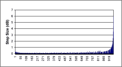
Figure 10 shows that most of the codes give attenuation values between 0 and -40dB. The 'delta', or dB step size between each attenuation value can be plotted in a similar manner to that in Table 2, to give a visual indication of the granularity of the steps:

Figure 11.
The granularity of the steps appears very evenly distributed, with differences in most of the steps being well under 0.5dB, only reaching 1dB at -41.6dB, with the penultimate 6dB step between -53.6 and -59.6. Repeated codes appear on the graph as 'zero' delta figures. This yields the kind of control range and granularity required in the most exacting pro-audio level controls.
There are, however, limitations to this approach. Obviously, this circuit has a reasonable control overhead (perhaps using look up tables to retrieve values and using some kind of ranging algorithm to obtain smooth volume transitions), but unlike the circuit in Figure 4, there is no conditional stability situation, so any combination of codes is fine. More seriously, variations in the tap-to-tap resistor matching between the first and second digital pots could mean that monotonicity is NOT guaranteed. Using a subset of the codes, hence coarser steps, would be one way of assuring monotonic steps, but this would at the expense of fine steps.
In theory, while the cascaded circuit of Figure 9 seems to give impressive results on initial investigation, the practical implementation of the circuit can be problematic.
Summary
The circuits of Figures 5 and 6 probably give the best compromise between price, complexity and performance for most situations. Controlled using a 3-wire interface, Maxim also offers the MAX5400/1/2 devices. These offer 256 taps for those applications needing slightly higher resolution and have a 3-wire protocol available for control.A similar version of this article appeared in the January 7, 2002 issue of EE Times magazine.
 電子發(fā)燒友App






評論