Introduction
The DS2740 high-precision coulomb counter is ideally suited for installation in either the host system or the battery pack of a portable electronic device requiring fuel-gauging technology. The coulomb counter provides high-precision current/net flow measurements to accurately measure battery capacity. The small footprint of it's μMAX packaging takes up little board space, and the 1μA max sleep mode supply current will not add unnecessary drain to the battery. Furthermore, the 1-Wire? interface only requires a single communication pin. Host supplied voltage and temperature measurements can be combined for a complete fuel-gauging system. This application note describes two recommended circuits for using the DS2740, one for host system installation and one for battery pack installation.Host System Installation
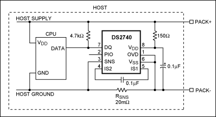
The schematic in Figure 1 illustrates a possible solution for using the DS2740 in the host system of a cell phone or personal digital assistant. The circuit shows both the DS2740 and host system being powered by an external battery pack. The pack could be a single-cell Lithium or triple-cell Nickel composition. The PACK+ and PACK- terminals represent the connection to the external battery pack. The 150Ω resistor from PACK+ to VDD of the DS2740 is for ESD immunity. The resistor helps limit current spikes into the part, and protect against over-voltage conditions. The other passive component on the VDD line is the 0.1μF capacitor. This capacitor helps to filter voltage spikes and keep the voltage within the specified 2.7V to 5.5V range.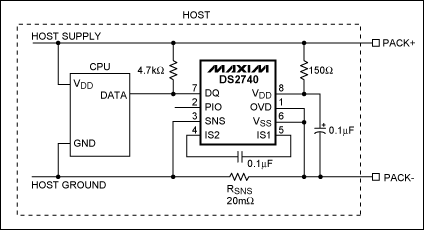
Figure 1. DS2740 installed in the host system.
The CPU data pin in Figure 1 is an open drain driver similar to the Data I/O (DQ) pin of the DS2740. The DATA and DQ pins are directly connected together, and a 4.7kΩ pullup resistor is used to pull the data line to a logic high. The DS2740 1-Wire bus speed control (OVD) pin is connected to VSS indicating standard 1-Wire timing protocol. For overdrive timing, the OVD pin should be tied to the VDD pin of the part. To monitor the voltage across the sense resistor (RSNS), the SNS pin is connected to the host side of RSNS and VSS is connected to the cell side. The current-sense input pins (IS1 and IS2) are connected to either end of a 0.1μF capacitor. This capacitor and the internal resistors provide a low pass filter for current spikes. The device ground, VSS, must always be connected to the negative terminal of the battery cell. The last pin, PIO, is an open-drain, general-purpose input/output driver, and is left floating in Figure 1. PIO is not necessary for proper device functionality, but usable options include driving an LED or vibrator.
The main benefit to installing the device in the host system is reduced cost. Only one device is needed in the host, rather than each battery pack having its own dedicated coulomb counter. The disadvantage is if the battery pack is removed from the host, the DS2740 will lose power. This causes the current accumulation data to be lost. Therefore, the host must periodically read and save the data from the DS2740.
Battery Pack Installation
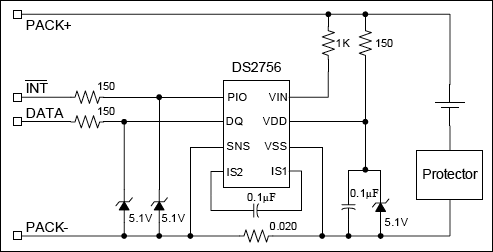
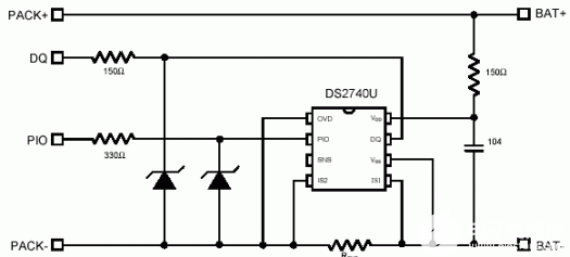
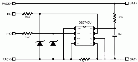
Figure 2 shows a schematic with the DS2740 mounted inside a single-cell Li+ battery pack. The PACK+, PACK-, DQ, and PIO nodes on the left represent the external contacts of the pack. As shown, the DS2740 should be installed on the contact side (as opposed to the cell side) of the protector. This prevents any unwanted charge paths through the DS2740. The protector may be any single cell protector.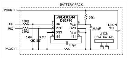
Figure 2. DS2740 installed in battery pack.
The primary differences between the pack installation, and the host installation are the PIO and DQ pins. For this example, these pins are routed to external contacts on the pack. These outside contacts require extra protection against ESD and voltage transients. The 150Ω and 330Ω resistors limit current spikes into DQ and PIO, respectively. The 5.6V Zener diodes protect the DQ and PIO pins from high voltage, yet do not interfere with normal operating voltages. Again, PIO is not necessary for device functionality and should be left open if not used. Also note that DQ is shown without a pullup resistor; this must be provided on the host side. All other components and pins were described in the host system example.
This circuit's main advantage is each cell has its own dedicated DS2740. Therefore, the coulomb count will remain accurate if the pack is removed, installed, charged or discharged. As long as the protector remains closed, and power is supplied to the DS2740, the current accumulation will continue. Each DS2740 has a unique 64-bit net address, so battery packs can also be uniquely identified.
Summary
The DS2740 is one of Dallas Semiconductor's most accurate coulomb-counting devices to date. The small μMax device is small enough to mount inside the host system or inside each battery pack, and requires only a single communication pin. Both host and battery pack applications have their own specific advantages. For host installation, cost is the big advantage, and in battery packs, dedicated hardware. Coupled with a host system providing temperature and voltage measurements, the DS2740 can build a complete fuel-gauging system.1-Wire is a registered trademark of Maxim Integrated Products, Inc.
 電子發(fā)燒友App








評論