This application note examines the specifications for T1, T3, E1, and E3 pulse masks, testing a transmission signal for pulse-mask compliance, and discusses some of the problems that can occur when testing multiport transmission devices. Dallas Semiconductor offers a line of multiport transceivers for both T1/E1 systems and T3/E3 systems as well as support hardware to ensure easier pulse-mask testing for multiport devices.
T1 Pulse Mask Template
The following are interface and pulse mask specifications for T1/E1/T3/E3 networks. The specifications for the digital networks were taken from the International Telecommunication Union (ITU) document G.703, October 1998, and the American National Standard for Telecommunications (ANSI) document ANSI T1.102-1993.The first and most common digital transmission system in North America is known as a T1 network (1.544Mbps). This system of transmitting digital data was developed in the mid-1960s for public telephone providers. Since then, T1 networks have changed their function from transmitting strictly digital voice conversations to transmitting large data packets, which is the core transmission technology for applications such as Wide Area Networks (WAN) and, of course, the Internet.
For each T1 line, the physical connection that a customer sees is always two twisted pair lines - one for the transmit data and one for the receive data. Both are differential pairs that are terminated with a 100Ω resistive load. To measure the pulse mask, the transmit data path is selected and measured at the end of the transmission line. Many T1 transceivers provide options to compensate for the resistive and capacitive loading of the transmission line by adjusting the amplitude of the T1 pulse. Dallas Semiconductor's T1 transceivers can be configured for both short-haul (DSX-1) lines, which can be up to 655 feet with 22 AWG cable, and long-haul (CSU) lines, which are rated to a maximum of -36dB of signal loss. This is normally referred to as the line buildout (LBO) of the transmission line. Within the short-haul (DSX-1) and long-haul (CSU) lines, Maxim's T1 transceivers can be set for the proper LBO.
Regardless of the way the T1 device is configured, the T1 signal must fit within the pulse mask at the end of the line when transmitting an isolated pulse. An isolated pulse is normally a positive puls e that is both preceded and followed by a certain number of zeros. The number of zeros required is determined by the spec ANSI T1.102-1993.
T1 pulse masks are normalized when displayed in graphical form with the nominal pulse amplitude of 1.0 inside the mask. The pulse amplitude is measured in the center of the pulse located at time T0 in Figure 1. If the amplitude at T0 is within the 2.4V and 3.6V, then the signal is scaled linearly to determine if it fits the pulse mask.
Table 1. T1 interface specification for pulse mask
| Nominal line rate | 1.544 Mbits/s |
| Medium | One balanced twisted pair shall be used for each direction of transmission. |
| Test load Impedance | A resistive test load of 100Ω ± 5%. |
| Pulse Amplitude | The pulse amplitude for a positive isolated pulse shall be between 2.4V and 3.6V. |
| Pulse Shape | The shape of every pulse that approximates an isolated pulse shall conform to the mask in Figure 1. This shape is shown in a normalized form, with the nominal pulse amplitude shown as 1.0. |
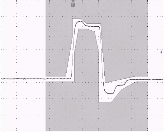
Figure 1. T1 Pulse (1.544 Mbits/s).
E1 Pulse Mask Template
There are other digital transmission systems besides T1 networks. One common system used widely in Europe and Asia is known as E1 (2.048 Mbits/s). From a broad overview, E1 networks are similar to the T1 networks with some minor differences in the line rate and number of channels per frame. There are other differences that exist as well. However, E1 networks still require two connectors (one used for the transmit data, the other for the receive data), a resistive termination at the end of the line, and the signals require that pulses meet a specified template. However, the spec for E1 requires that all the pulses meet the template and not just an isolated pulse. Another difference is the fact that E1 is tested at 0 ft, or at the source of the E1 pulse, while T1 pulses must meet the template for the entire line length. Please note there are two types of cables used in E1 mode: 75 Ohm coax cable and a 120 Ohm twisted pair. Both cables have different nominal amplitudes associated with them. For the 75 Ohm coax cable, the amplitude must be 2.37V ± 10% at T0. For the 120 Ohm twisted pair, the amplitude must be 3.0V ± 10%. This pulse must fit within this template and can not be scaled.Table 2. E1 interface specification for pulse mask
| Nominal line rate | 2.048 Mbits/s | |
| Single Ended | Differential Pair | |
| Medium | One coaxial pair shall be used for each direction of transmission. | One balanced twisted pair shall be used for each direction of transmission. |
| Test load Impedance | A resistive test load of 75Ω ± 5%. | A resistive test load of 120Ω ± 5%. |
| Pulse Amplitude | The nominal pulse amplitude for a positive isolated pulse shall be 2.37V. | The nominal pulse amplitude for a positive isolated pulse shall be 3.0V. |
| Pulse Shape | The shape of every pulse that approximates an isolated pulse shall conform to the mask in Figure 2. | |
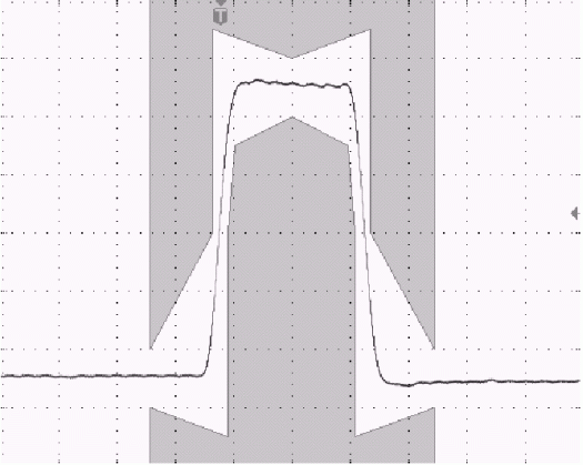
Figure 2. E1 Pulse (2.048 Mbits/s).
T3 and E3 Pulse Mask Template
When higher data rates are needed, T3 and E3 lines are often used. A T3 line (44.736 Mbits/s) can handle up to 28 T1 lines or 21 E1 lines while an E3 line (34.368 Mbits/s) can hold up to 16 E1 lines. Just as it is was with T1 and E1 networks, the T3 and E3 pulse must also meet a specified template. Refer to Figure 3 and Figure 4 for a graphical representation of each template. Both the T3 and E3 pulses are terminated with a 75 ohm resistive load. T3 pulses must meet template for the entire line length, which can be up to 450 feet, while E3 signals are measure at the source.Table 3. T3 interface specification for pulse mask
| Nominal line rate | 44.736 Mbits/s |
| Medium | One coaxial pair shall be used for each direction of transmission. |
| Isolated Pulse | A positive pulse that is preceded by two zeros and followed by one or more zeros. |
| Test load Impedance | A resistive test load of 75Ω ± 5%. |
| Pulse Amplitude | The pulse amplitude for a positive isolated pulse shall be between 0.36V and 0.85V. |
| Pulse Shape | The shape of every pulse that approximates an isolated pulse shall conform to the mask in Figure 3. This shape is shown in a normalized form, with the nominal pulse amplitude shown as 1.0. |
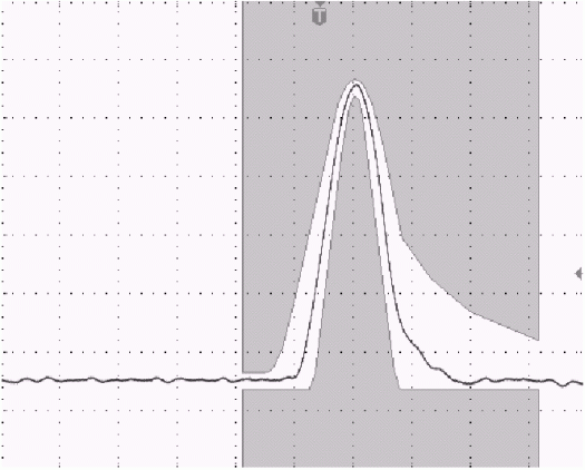
Figure 3. T3 Pulse (44.736 Mbits/s).
Table 4. E3 interface specification for pulse mask
| Nominal line rate | 34.368 Mbits/s |
| Medium | One coaxial pair shall be used for each direction of transmission. |
| Test load Impedance | A resistive test load of 75Ω ± 5%. |
| Pulse Amplitude | The pulse amplitude for a positive isolated pulse shall be 1.0V. |
| Pulse Shape | The shape of every pulse that approximates an isolated pulse shall conform to the mask in Figure 4. |

Figure 4. E3 Pulse (34.368 Mbits/s).
Pulse Mask Testing
Testing the pulse mask of a transmission device is a standard practice for not only the manufacturer, but also for the end users of telecommunication equipment. To perform this test, place your device in a mode where it is constantly transmitting a known data pattern. T1 and T3 networks have a spec to ensure that an isolated pulse is produced. For T1 signals, an isolated pulse is a pulse that is preceded by four zeros and followed by one or more zeros. An isolated pulse for T3 signals is a pulse that is preceded by two zeros and followed by one or more zeros. To reduce the reflections during the measurement of the pulse mask, it is highly recommended to maximize the number of zeros before the transmitting a one. E1 and E3 signals require that all pulses meet the specified template so there is not a spec for an isolated pulse.The transmission line is then loaded with the appropriate resistor value and connected to an oscilloscope for measurement. Figure 5 shows two common termination schemes. The first drawing is a diagram of the proper way to terminate the differential transmission line. Please note your scope must be set up to receive a differential signal for this to function properly. T1 networks require a 100Ω±5% resistive termination as the load therefore 50Ω±5% resistors are used on TTIP and TRING. For E1, which is 120Ωtermination, two 60Ω±5% resistors are used.
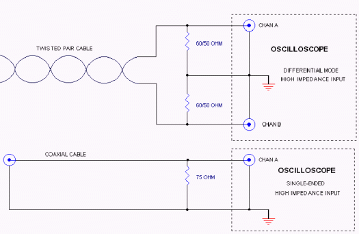
Figure 5. Line termination.
It is often desired to view the pulse mask of a transmission signal while at the same time using the remaining channels of the oscilloscope for other purposes. This requires the use of an active differential probe. There are several differential probes are on the market. It is recommend to use one that has the desired impedance termination and one that is rated for the oscilloscope you are using. Tektronix, LeCroy and HP all make differential probes with termination that can be used with T1 or E1 transmission signals.
The second termination scheme in Figure 5 is for single ended transmission lines. To measure this pulse mask, simply add the termination resistor as close as possible to the high impedance input of the oscilloscope. This will minimize the reflections and noise seen by the oscilloscope when making the pulse mask measurement.
When different line build outs (LBO) are required such as in the case with T1 and T3 networks, a line simulator is usually added to provide the proper capacitive loading on the transmission line. Please see Figure 6.
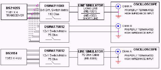
Figure 6. Pulse mask testing block diagram.
Problems with Testing Pulse Mask
A problem develops when you have multi-port transmission devices. There are a number of multi-channel oscilloscopes on the market that can measure multiple pulses at once, but many of the line simulators are single-port only. A Nx1 switch matrix is required to fully utilize both the line simulator as well as the ocilliscope without constantly moving cables for measurement. Dallas Semiconductor/Maxim had developed two matrix cards, which solves this problem and provides a GPIB interface for communicating to the board remotely. Both matrix boards were designed to be impedance controlled to reduce reflections in the measured signal. Also each matrix board has a separate transmit and receive path for each signal path. This is useful when testing for receiver sensitivity.The following is a block diagram representation of a multi-port T1E1 Single Chip Transceiver such as the DS21Q55 and a T3/E3 Line Interface Unit such as the DS3154 with the associated hardware required for making a pulse mask measurement.
Notice the DSMAT110X8 between the DS21Q55 and the line simulator as well as the DSMAT75X12 between the DS21Q55 and the oscilloscope. The DSMAT110X8 is an 8x1 matrix card specifically designed for differential telecom signals that require 100Ωto 120Ωimpedance matching. The DSMAT75X12 is a 12x1 matrix with 75ohm impedance matching and is designed for single ended signals. The DS21Q55 can operate in both T1 and E1 modes with a variety of termination configurations: 75/100/120 ohm. With so many configurations, it becomes difficult to quickly check to see if the device will meet pulse mask in all possible applications for every port. The two matrix cards make this much easier by allowing the user to isolate signals on a certain port through a specified path. For example in T1 mode, a differential signal of 100Ωis required and the device must meet template up to 655 feet. By using the DSMAT110X8 card and the line simulator, the pulse mask can be measured for all possible Line Build Outs (LBO). However in E1 mode, a differential signal of 120Ωor a single ended signal of 75Ωmay be selected depending on the application. Therefore, you must only use the appropriate matrix so you do not short one of the differential signals from the E1 twisted pair cable. Pulse mask testing for E1 is done at 0 feet only so the line simulator is set for pass through mode. It simply depends on how the device is configured.
The second diagram in Figure 6 shows another multi-port device, the DS3154. This device is similar only in the fact that it can switch between two different transmission modes, which in this case are T3 and E3. Fortunately, the spec for T3 and E3 call for 75Ωtermination so only the DSMAT75X12 card is necessary. But again for T3 mode, the device must meet template for the entire Line Build Out so a line simulator is necessary. For E3 mode the line simulator is set in pass through mode.
As the port counts increase on the data transmission equipment, so does the need for testing the transmission signal for pulse mask compliance quickly and reliably.
Maxim has developed solutions to satisfy this need for both T1/E1 applications as well as T3/E3 applications.
 電子發(fā)燒友App








評論