In recent years, news about communications networks technology always seems to involve some pronouncement on the urgent need for more bandwidth. The facts still bear repeating: A growing number of people with telephones, faxes, modems, and computers are, through the exchange of terabytes of digitized information (videos, images, modeling procedures, as well as data and voice), demanding a larger share of the carrier spectrum. In response, high-tech communications companies who thrive on growth are competing to feed this appetite for bandwidth. Over the past decade, major resources have gone into developing fiber-optic networks in which light waves transport information at rates of gigabits per second through optical fibers finer than the human hair.
The stakes are very high. In a May 2000 news release, The Aberdeen Group (Boston, MA), an IT consulting firm, predicted that "The optical network market, excluding SONET elements, will grow to $17.7 billion by 2003. The suppliers that can deliver the technologies that solve the problems that carriers face, will be the ones to succeed."
The use of the plural in "suppliers" and "technologies" highlights a key issue in this article. The burgeoning communications network is highly complex. While a few large companies tend to dominate the global deployment of the optical network, behind the scenes there is a fusion of technologies developed by multiple companies, each with specialized technological expertise. Maxim falls into this latter category; we have designed a family of variable resistors especially for optical transceiver modules. A look at where Maxim's resistors fit into the grand scheme of communications networks reveals something about the way the communications industry develops solutions.
Identifying the Big Picture
Optical transceiver modules are designed and built by a variety of manufacturers. Applications for the modules include Synchronous Optical NETwork (SONET) and Synchronous Digital Hierarchy (SDH), Asynchronous Transfer Mode (ATM), Fiber Distributed Data Interface (FDDI), Fiber Channel, Fast Ethernet and Gigabit Ethernet. The names of these systems reflect the range of internationally defined transmission protocols and standards. On the other hand, the modules themselves were initially developed without definitive physical characteristics.Recognizing the need for conformity, if their products were to succeed, a group of manufacturers banded together and developed a multi-source agreement (MSA) for transceiver modules in 1998. The group consisted of AMP Incorporated, Hewlett-Packard Company, Lucent Technologies Microelectronics Group, Nortel (Northern Telecom), Siemens AG-Fiber Optics, and Sumitomo Electric Lightwave Corp. These parties agreed to cut the size of their modules in half (to 0.535 inch in width) and specified a set of module packages and pin-outs that would be interchangeable among the variety of RJ-45-style (including duplex LC, MT-RJ, and SC/DC) optical connectors used in high-speed fiber-channel applications.
Currently, a new consortium is drafting a new MSA for transceiver modules, reflecting a larger contingent of manufacturers and a new generation of modules. These multi-source manufacturers now include Agilent Technologies, Glaze Network Products, E2O Communications, Finisar, Fujikura Technology America, Hitachi Cable, Infineon Technologies, IBM, Lucent Technologies, Molex, OCP, Picolight, Stratos Lightwave, Sumitomo Electric Lightwave, and Tyco Electronics. The module specification is now called small form-factor pluggable (SFP) and covers expected transmission rates of up to 5.0Gb/s. The specifications reflect the industry's drive for high-density signal transmission in hot-pluggable modules of smaller size and higher speed.
To find where our resistors come into the picture, it helps to understand some basics about the transceiver module. The module converts incoming light waves to electrical signals and outgoing electrical signals back to light. Of fundamental significance, the optical transceiver is based on semiconductor laser technology. The module is a printed circuit board (PCB), and the optical source for the coveted bandwidth is a tiny semiconductor chip: a light-emitting or laser diode. At frequencies in the near-infrared spectrum, the laser's output can be modulated in tens of GHz, a capacious bandwidth.
The following briefly summarizes a signal path through the transceiver module. The receiving port connects to incoming light fibers. A photodetector diode converts the light to electrical signals, which are then amplified so that clock and data signals can be recovered, de-multiplexed, and sent out through the electrical interface. The photodetector requires an automatically power-controlled bias circuit to provide a constant operating voltage (see Figure 1). Meanwhile on the transmitting side of the module, electrical clock and data-bit signals are synthesized and latched and sent to the laser driver. Finally, the laser driver sends the signal as electrical current to the laser diode, which converts electron energy to light.
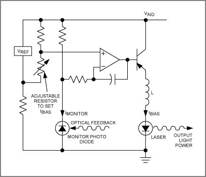
Figure 1. Typical average power control circuit using a monitor photodiode and adjustable resistor to set bias current.
In some designs that use laser diodes, a photodetector monitors the laser diode output and, in a feedback loop, reconverts the light back to electrical circuits that measure the laser's actual output power. This feedback stabilizes the laser output power. The optical feedback is a complicating drawback to this design. However, the latest laser technology, vertical cavity surface emitting lasers (VCSELs), often do not require a photodetector because of exceedingly low current.
The laser driver must do two things: it must maintain a consistent DC-bias current to set the laser operating point, and it must maintain a modulation current to carry the signal. As manufacturers strive to increase signal throughput in transceivers, the laser source must be carefully characterized for operating constants in order to control the light output.
The Laser Diode and VCSEL
The Fabry-Perot type of laser diode emits a coherent light beam from the narrow, beveled edge of the chip, with reflecting mirrors incorporated at the edges or stationed outside the chip. For the future of the communications industry however, a more promising laser source is the VCSEL. As its name suggests, the VCSEL vertically emits the laser beam from a circular cavity 5 to 25 micrometers in diameter at the top (the bottom is a future possibility) of the chip. The mirrors are incorporated as an integrated array on both ends of the cavity—a design known as a "distributed Bragg reflector." In the future, parallel optical interconnects using multi-element VCSEL arrays could enable terabyte throughput.Academic and corporate institutions are vigorously developing VCSEL designs for more widespread deployment. Compared to edge-emitters, the VCSEL requires less current and has a lower lasing threshold (1mA or 2mA versus 30mA). At this level, simple current control is often sufficient without the extra photodetector to monitor output. The VCSEL's emitting aperture is measurably larger, which means that the output beam's angle of divergence (a measure of dispersion) is significantly smaller. There are several manufacturing and processing advantages, as well. The die is much smaller, allowing more VCSELs to be packed on a wafer with more interconnects; all the VCSELs on an entire wafer can be tested at once. Lastly, the VCSEL is more robust in operation than a laser diode, with a longer life expectancy and lower failure rates.
Whether laser diode or VCSEL, the laser emitter in any optical transceiver is a semiconductor whose photoelectric effects depend on the interplay of current, voltage, and resistance. Some of the following factors affect safety and performance:
- Laser output is exceedingly sensitive to temperature.
- Laser power output tends to change over the life of the laser and this aging increases with temperature.
- As VCSELs operate at significantly lower power and temperature than diodes, the failure rate over time is proportionately lower.
- The laser emitter needs to be protected from random power transients as well as transients during power-on and power-off.
- Even though a laser's near-infrared light is invisible to humans, a beam entering the eye is still focused on the retina and can cause permanent damage. Because of potentially serious effects on personal safety and laser function, regulations require that laser power output be limited to a few hundred microwatts.
From the big-picture viewpoint, we can delineate the accumulated facts as follows:
- Exploding demand for bandwidth leads to the development of optical networks.
- Optical networks use optical transceiver modules to physically convert optical and electrical signals.
- Manufacturers of transceiver modules are driven to decrease physical size and increase signal throughput to multiple gigabits per second.
- Transceiver modules use photodiodes to receive light signals and laser diodes or VCSELs to send light signals.
- As data rates continually increase, modules' photo-active components require ever more precise, reliable power control in order to prevent laser failure, prolong life expectancy, and/or operate within desired output parameters.
A Niche Industry
While not in any strict sense one of the communications companies, Maxim brings expertise to the table in several pertinent technologies: digitally controlled variable resistors and potentiometers, EEPROM, temperature sensors, and extremely low-power CMOS methods. In response to the needs of gigabit optical technology, Maxim has produced a product family with a new range of features.With the DS1845 Dual Potentiometer with EEPROM, Dallas Semiconductor (a wholly owned subsidiary of Maxim Integrated Products) designed the semiconductor industry's first potentiometer with integrated memory, specifically for service in pluggable gigabit transceiver modules. The DS1845 combines two linear-taper potentiometers with 256 bytes of EEPROM, which is required by the MSA standards. The higher-resolution, 256-position potentiometer can be used to control modulation current and the 100-position potentiometer can be used to control bias current. Users configure both outputs and store the wiper settings and required serial ID data in the on-chip, nonvolatile EEPROM memory for reference during operation.
In modules that aim to shrink into SFPs, more densely integrated components that combine memory and two separately configured potentiometers save space by replacing multiple parts. Furthermore, the DS1845's 2-wire interface meets the transceiver producers' requirement for in-circuit programmability and is compatible with existing 2-wire EEPROM.
To meet more a specialized need, Dallas Semiconductor developed the DS1846, which combines three linear taper potentiometers with nonvolatile memory and a CPU supervisor in reduced TSSOP packaging. This level of integration in such a small chip saves board space and cuts cost and procurement delays, expediting product development. As with the DS1845, the nonvolatile memory is used to configure and store application-specific calibration data. And, to control wiper settings for each potentiometer, there's also memory space available for user-specific data.
The DS1846's on-chip micromonitor tracks voltages. On detecting an out-of-tolerance voltage level, the micromonitor initiates and holds a system reset until safe operating conditions return. The micromonitor is programmable for various voltage levels and includes a manual reset.
The third potentiometer can be used to monitor another variable or to provide a coarse trim for one of the other resistors.
Intended for demanding laser applications, the DS1847 and DS1848 compensate for the laser's thermal characteristics over temperature ranges (see Figure 2). The DS1848 has an extra 128 bytes of general-purpose EEPROM; otherwise the two are alike. The chips store resistance characteristics relative to temperature in an onboard look-up table (LUT). An integrated temperature sensor constantly measures and reports temperatures during laser operation. The DS1847 or DS1848 compares the reading to the value stored in the LUT and adjusts resistance according to the designer's defined resistance characteristics. The value determined by the temperature sensor is also stored in EEPROM (updated every 10msec), and is available to the user over the 2-wire bus. It should also be noted that the DS1847 and DS1848 operate automatically. As a temperature change is detected, control circuits automatically adjust resistance to achieve the compensating current value without any user intervention.
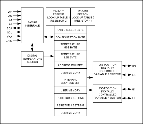
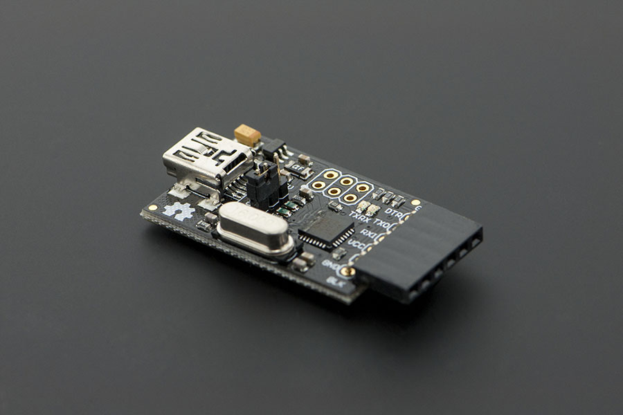
Figure 2. Variable resistors, designed for optical transceivers like this one, automatically calibrate each diode more accurately than the older, mechanical-trim potentiometers.
As a whole, all Maxim circuits employ a low-power CMOS technology that contributes to holding down a sensitive power budget. All circuits operate throughout the industrial temperature range and with both 3V and 5V power supplies.
Clearly, in a huge, complex, driven market like optical communications networks, many players operate at many levels. The success of the laser, the star in a new and exotic technology, can depend on a comparatively old and familiar player, the humble resistor. Of course, Maxim's caveat to the moral of this fable would be, "It's not your grandfather's resistor any more."
 電子發(fā)燒友App







評(píng)論