TI公司的AWR1243是單片77GHz和79GHz頻率調(diào)制連續(xù)波(FMCW)收發(fā)器,具有基于分?jǐn)?shù)N PLL的超精密啁啾引擎,簡化了汽車?yán)走_(dá)傳感器在76-81GHz的實現(xiàn)方案.采用低功耗45nm RFCMOS工藝,單片實現(xiàn)了內(nèi)置PLL和A2D轉(zhuǎn)換器的3TX,4RX系統(tǒng).TX發(fā)送功率12dBm,RX噪音15dB (76-77GHz), 16dB(77-81GHz),1MHz時的相位噪音–94 dBc/Hz (76-77 GHz),–91 dBc/Hz (77 - 81 GHz),內(nèi)置了校準(zhǔn)和自測試等功能.主要用在自動高速公路駕駛,自動緊急剎車和自適應(yīng)巡航控制.本文介紹了AWR1243主要特性,功能框圖,短中遠(yuǎn)距離雷達(dá)框圖,參考電路,以及AWR1443 BoosterPack?評估板主要特性,框圖,電路圖,材料清單和PCB設(shè)計圖.
The AWR1243 device is an integrated single-chip FMCW transceiver capable of operation in the 76- to 81-GHz band. The device enables unprecedented levels of integration in an extremely small form factor. AWR1243 is an ideal solution for low power, self-monitored, ultra-accurate radar systems in the automotive space.
The AWR1243 device is a self-contained FMCW transceiver single-chip solution that simplifies the implementation of Automotive Radar sensors in the band of 76 to 81 GHz. It is built on TI’s low-power 45-nm RFCMOS process, which enables a monolithic implementation of a 3TX, 4RX system with built-in PLL and A2D converters. Simple programming model changes can enable a wide variety of sensor implementation (Short, Mid, Long) with the possibility of dynamic reconfiguration for implementing a multimode sensor. Additionally, the device is provided as a complete platform solution including reference hardware design, software drivers, sample configurations, API guide, and user documentation.
AWR1243主要特性:
FMCW Transceiver
Integrated PLL, Transmitter, Receiver, Baseband, and A2D
76- to 81-GHz Coverage With 4 GHz Available Bandwidth
Four Receive Channels
Three Transmit Channels (Two Can be Used Simultaneously)
Ultra-Accurate Chirp Engine Based on Fractional-N PLL
TX Power: 12 dBm
RX Noise Figure:
15 dB (76 to 77 GHz)
16 dB (77 to 81 GHz)
Phase Noise at 1 MHz:
–94 dBc/Hz (76 to 77 GHz)
–91 dBc/Hz (77 to 81 GHz)
Built-in Calibration and Self-Test
Built-in Firmware (ROM)
Self-calibrating System Across Frequency and Temperature
Host Interface
Control Interface With External Processor Over SPI
Data Interface With External Processor Over MIPI D-PHY and CSI2 V1.1
Interrupts for Fault Reporting
ASIL B Capable
AECQ100 Qualified
AWR1243 Advanced Features
Embedded Self-monitoring With No Host Processor Involvement
Complex Baseband Architecture
Option of Cascading Multiple Devices to Increase Channel Count
Embedded Interference Detection Capability
Power Management
Built-in LDO Network for Enhanced PSRR
I/Os Support Dual Voltage 3.3 V/1.8 V
Clock Source
40.0-MHz Crystal With Internal Oscillator
Supports External Oscillator at 40 and 50 MHz
Easy Hardware Design
0.65-mm Pitch, 161-Pin 10.4 mm × 10.4 mm Flip Chip BGA Package for Easy Assembly and Low-Cost PCB Design
Small Solution Size
Supports Automotive Temperature Operating Range
AWR1243應(yīng)用:
? Automated Highway Driving
? Automatic Emergency Braking
? Adaptive Cruise Control

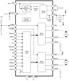
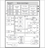
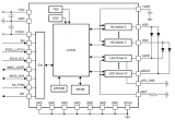
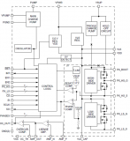
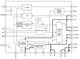
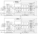
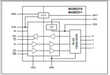
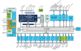
圖1.AWR1243功能框圖
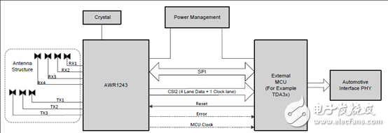
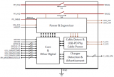
圖2.AWR1243短中遠(yuǎn)距離雷達(dá)框圖
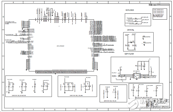
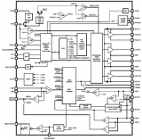
圖3.AWR1243參考電路圖
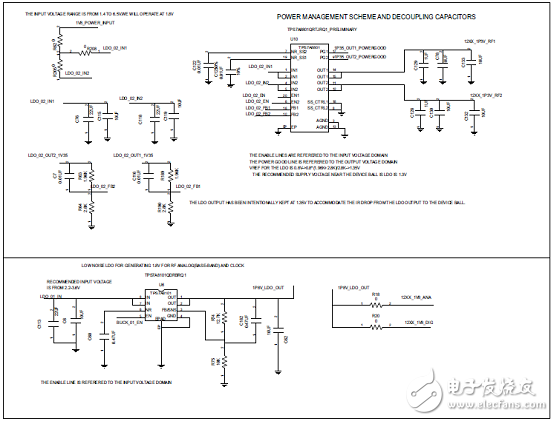
圖4.AWR1243低噪音LDO電路圖
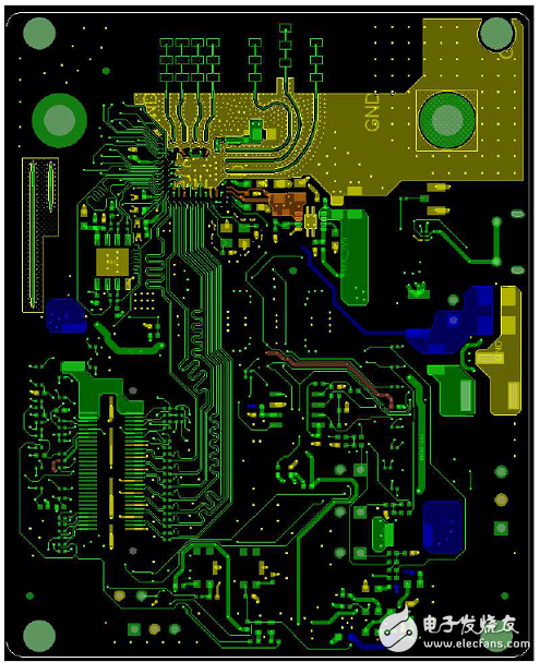
圖5.AWR1243參考電路PCB布局圖(頂層)
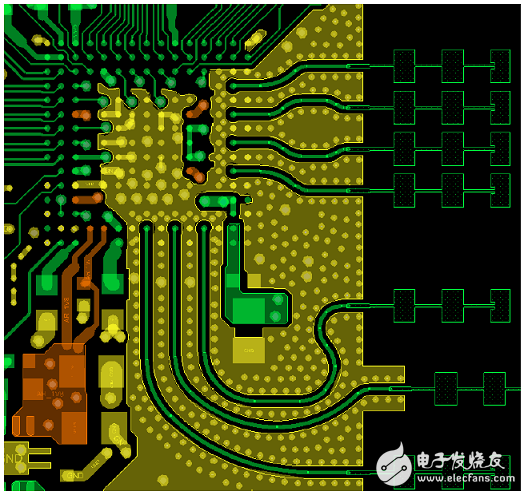
圖6.AWR1243參考電路PCB布局圖(頂層放大圖)
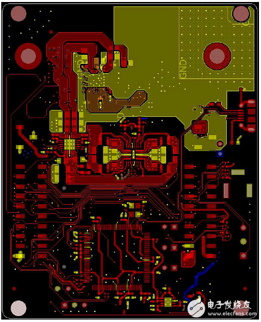
圖7.AWR1243參考電路PCB布局圖(底層)
AWR1443 BoosterPack?評估板
The AWR1443 BoosterPack? is an easy-to-use evaluation board for the single-chip AWR1443 mmWavesensing device from TI, with direct connectivity to the TI MCU LaunchPad? ecosystem. The evaluationboard contains everything needed to start developing on a low-power ARM?-R4F controller. Theevaluation board includes onboard emulation for programming and debugging, onboard buttons, andLEDs, for quick integration of a simple user interface. The standard 20-pin BoosterPack headers make the evaluation board compatible with a wide variety of TI MCU LaunchPads and enables easy prototyping.
The AWR1243 BoosterPack is an evaluation board for the AWR1243 mmWave high-performance frontend. The evaluation platform enables raw capture of ADC data from the front end and evaluation of RFperformance.
AWR1443 BoosterPack?評估板主要特性:
? 40-pin LaunchPad standard that leverages the LaunchPad ecosystem
? XDS110-based JTAG emulation with serial port, for onboard QSPI flash programming (for AWR1443)
? Backchannel UART through USB to PC, for logging purposes
? Onboard antenna
? 60-pin high density (HD) connector, for raw ADC data over CSI, or the high-speed debug interface
? Onboard CAN transceiver (for AWR1443)
? One button and two LEDs, for user interaction
? 5-V power jack, to power the board
AWR1443 BoosterPack?評估板包括:
? AWR1443BOOST or AWR1243BOOST
? Mounting brackets, screws, and nuts, to allow placing the PCB vertical
? Mirco USB cable to connect to the PC
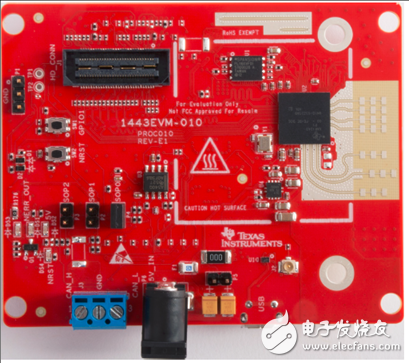
圖8.AWR1443 BoosterPack?評估板外形圖
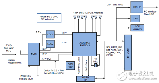
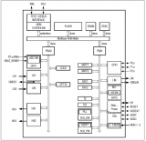
圖9.AWR1443 BoosterPack?評估板框圖
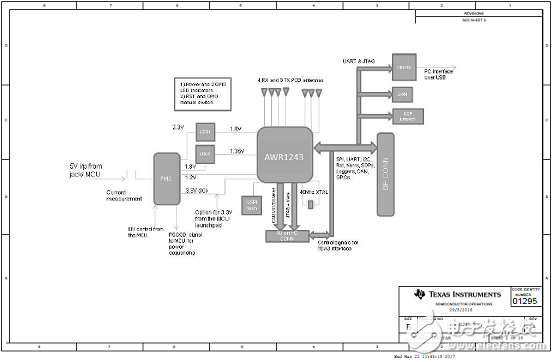
圖10.AWR1443 BoosterPack?評估板電路圖(1)
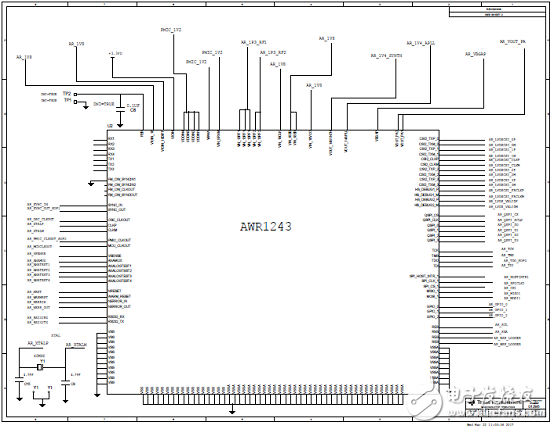
圖11.AWR1443 BoosterPack?評估板電路圖(2)
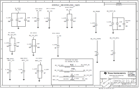
圖12.AWR1443 BoosterPack?評估板電路圖(3)
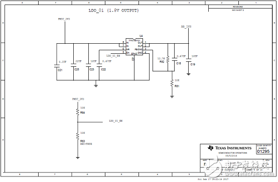
圖13.AWR1443 BoosterPack?評估板電路圖(4)
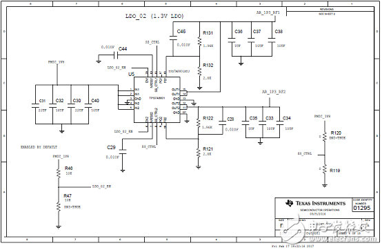
圖14.AWR1443 BoosterPack?評估板電路圖(5)
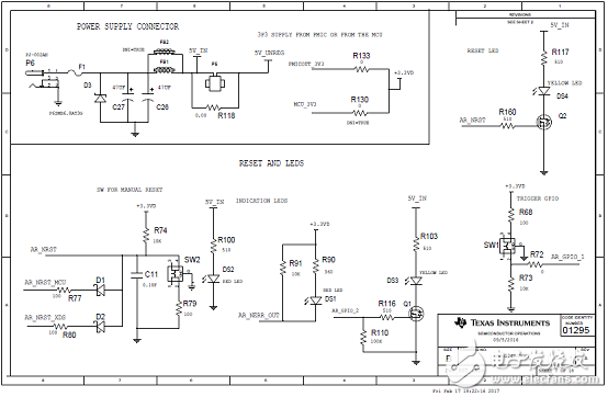
圖15.AWR1443 BoosterPack?評估板電路圖(6)
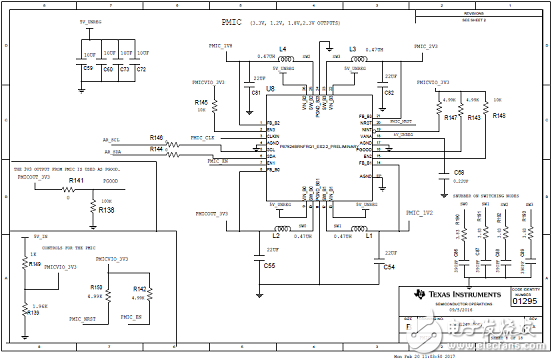
圖16.AWR1443 BoosterPack?評估板電路圖(7)
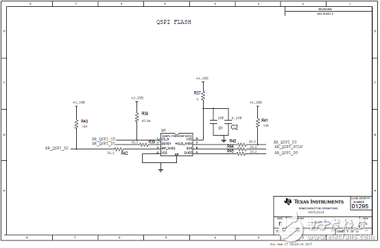
圖17.AWR1443 BoosterPack?評估板電路圖(8)
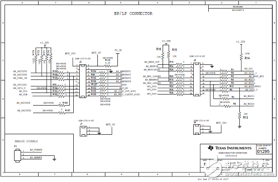
圖18.AWR1443 BoosterPack?評估板電路圖(9)
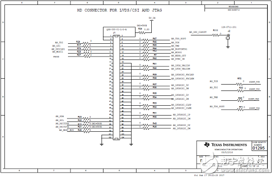
圖19.AWR1443 BoosterPack?評估板電路圖(10)
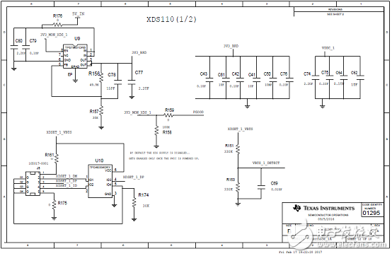
圖20.AWR1443 BoosterPack?評估板電路圖(11)
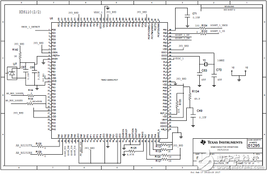
圖21.AWR1443 BoosterPack?評估板電路圖(12)
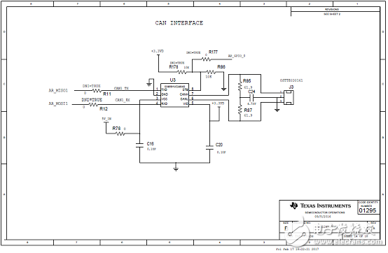
圖22.AWR1443 BoosterPack?評估板電路圖(13)
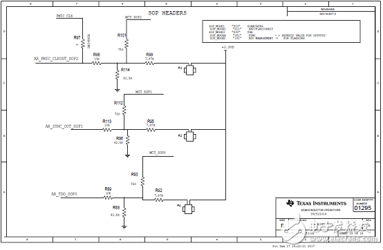
圖23.AWR1443 BoosterPack?評估板電路圖(14)
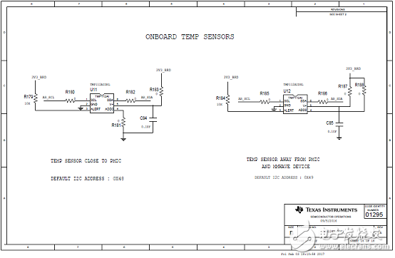
圖24.AWR1443 BoosterPack?評估板電路圖(15)
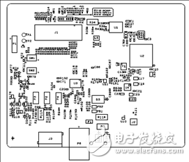
圖25.AWR1443 BoosterPack?評估板PCB設(shè)計圖(1)
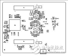
圖26.AWR1443 BoosterPack?評估板PCB設(shè)計圖(2)
 電子發(fā)燒友App













評論